Eureka AIR delivers breakthrough ideas for toughest innovation challenges, trusted by R&D personnel around the world.

Combined axial piston liquid pump and energy recovery pressure exchanger

a technology of energy recovery pressure exchanger and axial piston, which is applied in the structure of a rotary axial piston pumping unit, can solve the problems of transducer loss, unfulfilled challenge, and extremely difficult to achieve and maintain high operating efficiency for economical operation, and achieve the effect of minimizing the number of moving parts, efficient deployment and optimal benefit of recovered energy

Inactive Publication Date: 2010-09-21
OCEAN PACIFIC TECH
View PDF18 Cites 51 Cited by
  • Summary
  • Abstract
  • Description
  • Claims
  • Application Information

AI Technical Summary

Benefits of technology

[0029]It is a primary object of the present invention to provide further refinements beyond the art described above for enhancements in efficiency, reliability and cost effectiveness in the evolution of this field of endeavor, including simplification with fewer moving parts for long term reliability and low maintenance, thus accomplishing lower capital costs and lower operating costs.
[0031]It is a further object to implement the combination pump utilizing proven aspects of rotor-drum rotational sliding valve port technology for both the APP (axial piston pump) function and the PX (pressure exchanger) function in novel combination that provides optimal benefit of recovered energy, particularly as applied to an RO desalination system.
[0032]It is a further object to minimize the number of moving parts in the combination pump and pressure exchanger.
[0033]It is a still further object that the implementation of the combination machine allows the pistons to rotate freely within the cylinders as practiced in known swash-plate type hydraulic motors and pumps, since this practice is considered beneficial with regard to long term reliability through even distribution of wear throughout the cylinder walls and pistons.
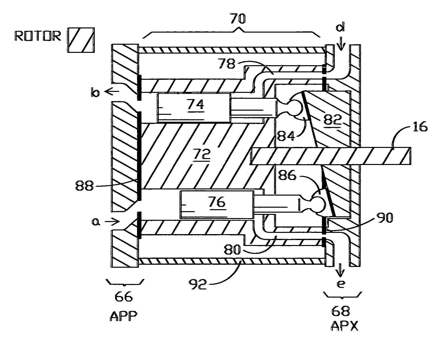
[0035]The above mentioned and other objects and advantages have been realized in a rotor-drum type APP (axial piston pump), for primary liquid flow pressuring, that incorporates a PX (pressure exchange) hydraulic motor function for energy recovery from a secondary liquid flow such as the brine discharge from an RO seawater desalination system. A single rotor-drum contains a set of dual function cylinders each containing a dual function axial piston. The system can be optimized for efficient deployment in an RO system to provide benefits including unusual simplicity, compact machine size and low capital and operating costs. Long term reliability is enhanced by the pistons being made free to rotate in place within the cylinders for uniform distribution of frictional wear. Special materials, tolerances and configurations such as lubrication ducts directed to the swash-plate sliders enable liquid such as seawater to act as lubricant.

Problems solved by technology

Whether through sophisticated computer automation or the diligence of skilled human operating staff, high operating efficiency for economical operation is extremely difficult and challenging to accomplish and maintain since it has to take into account many short term and long term side effects and variables such as temperature of liquids and machines, variation in demand and removal of desalinated product, power line voltage variations, membrane condition, leakage, wear degradation of machinery, seals, valves, etc.
However, the concept of combining the hydraulic AP (axial piston) pump and hydraulic PX (pressure exchanger) motor in a single integral unit for use with non-oily liquids such as seawater remains a challenge unfulfilled by known art, subject to the discovery and development of new configurations with novel deployment of recently developed materials.
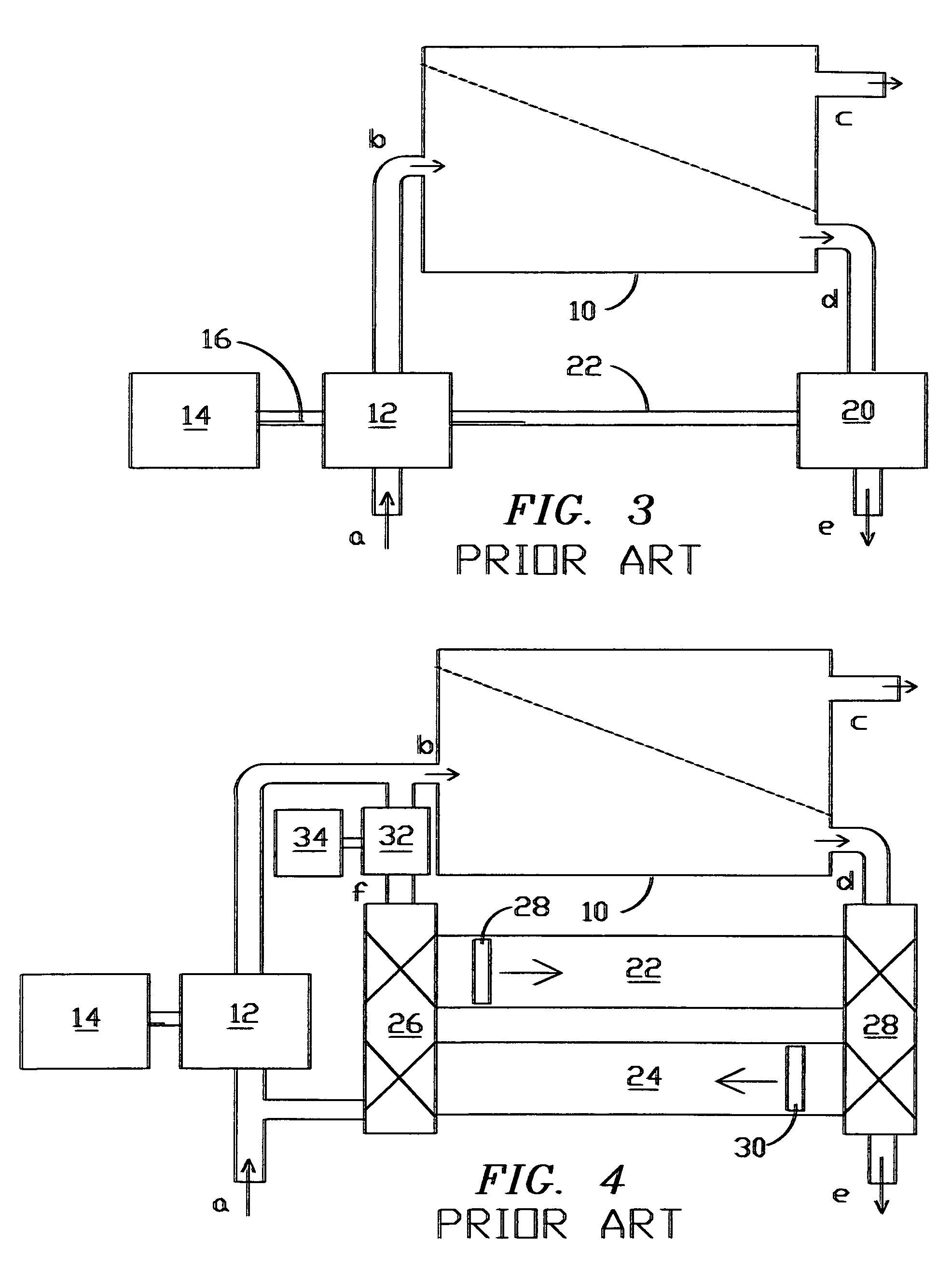
In principle, energy could be recovered in an RO process as in FIG. 3 utilizing a hydraulic swash-plate type motor driven from the output brine stream, shaft-coupled to assist the input pump which could also be of the hydraulic swash-plate type, subject to capability of handling seawater; however such an approach would require two hydraulic machines of special custom design and manufacture to operate with water and would still be subject to the compounding of transducer losses in both machines with the resultant limitation on efficiency as described above in connection with FIG. 3.

Method used


Image

  • Combined axial piston liquid pump and energy recovery pressure exchanger
  • Combined axial piston liquid pump and energy recovery pressure exchanger
  • Combined axial piston liquid pump and energy recovery pressure exchanger

Examples


Embodiment Construction

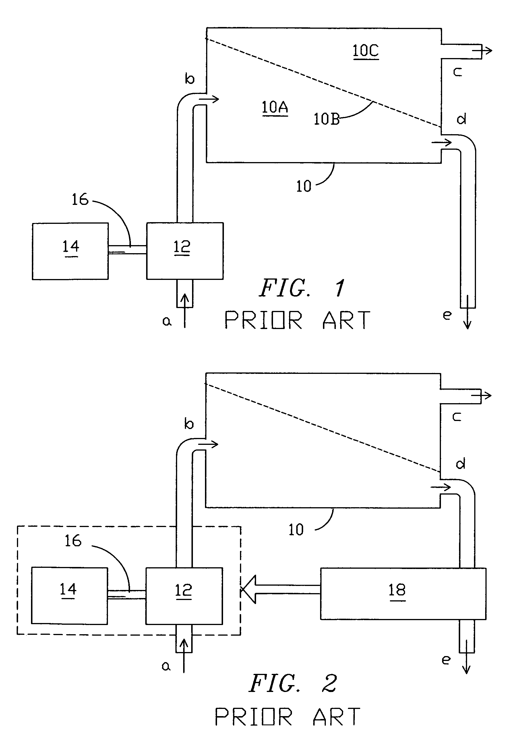
[0053]FIGS. 1 and 2 have been described above in connection with the discussion of background of the invention. FIGS. 3-6 have been described above in connection with the discussion of known art.

[0054]FIG. 7 is a functional block diagram showing a single machine 64 combining a pump and a pressure exchanger in accordance with the present invention, deployed as the primary pump in a reverse osmosis desalination system. The machine 64 is a self-contained unit that includes the main primary flow pressure pump and a secondary (brine) flow-actuated energy exchanger PX assisting the pump AP.

[0055]Machine 64 is connected to RO unit 12 seawater intake flow path (ports / nodes a and b) which receives seawater at low pressure from pre-conditioning apparatus, and the brine output flow path (ports / nodes d and e) in the simple and direct manner shown: all that is needed additionally to operate the RO unit 12 is the electric motor 14 driving shaft 16, seawater acquisition and preconditioning apparat...


PUM


Abstract

A pumping machine, that can serve a system as the sole main pump for pressurizing a primary liquid flow, incorporates, in a single machine, a rotor-drum type AP (axial piston) pump and a PX (pressure exchanger) that recovers energy from a secondary liquid flow such as the brine discharge from an RO seawater desalination system, with benefits including fewer moving parts and small machine size along with lower capital and operating costs. A single rotor-drum containing the cylinders and pistons is located between two end blocks, one or both configured with manifold passageways, ports and sliding valves. A swash-plate at one end reciprocates the pistons axially when the rotor-drum is rotated. Two working chambers, primary and secondary, are formed at opposite ends of a single piston in each cylinder, thus enabling the single rotor-drum to function as a primary liquid-pressurizing axial pump (AP) with sliding valves at the primary end enabling primary liquid pumping, and as a secondary outflow-driven pressure exchanger (PX) recovering energy from pressure drop in the secondary liquid flow and thus contributing work to primary pumping, saving energy and reducing operating costs.

Description

FIELD OF THE INVENTION[0001]The present invention relates to liquid pumps and more particularly it relates to structure of a rotary axial piston pumping unit, that can serve as the primary system pump pressurizing a system destination, such as an RO (reverse osmosis) chamber, the pumping unit incorporating a pressure exchanger for reducing the operating cost by recovering energy from a secondary flow that may be an unwanted byproduct from the process, for example brine discharged at high pressure from an RO seawater desalination system.BACKGROUND OF THE INVENTION[0002]The functional block diagram of FIG. 1 shows a basic form of an RO (reverse osmosis) filtering system of known art without energy recovery, e.g. a small system for an individual home or small business. A pressurized RO enclosure 10 receives a water supply at its input node “a” at elevated pressure, either from municipal water mains or, as shown pressurized by a pressure pump 12 driven by a motor 14, typically electric....

Claims


Application Information

Patent Timeline
Patent Type & Authority Patents(United States)
IPC IPC(8): B01D61/06B01D61/08B01D63/00
CPCB01D61/025B01D61/06B01D61/08B01D61/10F04B1/20F04B5/02B01D2313/24B01D2313/246Y02W10/37Y02A20/131B01D61/081
Inventor MACHARG, JOHN P.
Owner OCEAN PACIFIC TECH
Why Eureka
Eureka Blog
Learn More