
Method of recovering copper from a dilute metal containing solution

a metal containing solution and copper technology, applied in the field of recovering copper, can solve the problems of acidic metal containing water in mines containing sulphide minerals, harmful waste to the environment, wastewater from abandoned sulphide mines, etc., and achieve the effect of reducing energy consumption

Active Publication Date: 2021-03-02
ELMERY OY
View PDF5 Cites 0 Cited by
  • Summary
  • Abstract
  • Description
  • Claims
  • Application Information

AI Technical Summary

Benefits of technology

This invention is about a new method for removing copper from mining waters without using additional chemicals. The method uses a process called electrodeposition-redox replacement, which involves cycling between electrodeposition and redox replacement steps. This method is more energy-efficient, especially when the ratio of iron to copper is high. It is also cost-effective and environmentally friendly. The recovered copper can be used as a raw material for copper smelting without being affected by any leftover iron. Overall, this invention provides a novel and efficient way to recover copper from mining waters.

Problems solved by technology

Wastewater from abandoned sulphide mines is considered as harmful waste for the environment.
Mines containing sulphidic minerals end up suffering from acidic metal containing waters with time, when minerals or ore body are exposed to air and water.
However, electrowinning of for example copper as a high purity product from mining waters where it is present at low concentrations is challenging and economically unfeasible.
However, none of these publications aims to recover copper or more noble metals from dilute metal containing solutions such as mining waters using repeated electrodeposition and redox replacement method, with a lower energy consumption compared to conventional electrodeposition or electrowinning, particularly when said metals are present at low concentrations.
Nevertheless, none of these publications is using SLRR or related methodology for copper recovery from impure mining waters and using mainly iron as sacrificial metal; in the above mentioned publications, Pb is mostly used as a sacrificial metal for copper deposition, all solutions are synthetic and the research aim is to create functional surfaces and coatings for laboratory scale measurements.
In this invention, however, the methodology is developed for copper removal and / or recovery from dilute copper-iron bearing solutions such as mining waters, a task in which copper recovery by electrochemical methods has not been an industrially attractive option.

Method used


Image

  • Method of recovering copper from a dilute metal containing solution
  • Method of recovering copper from a dilute metal containing solution

Examples


example 1

nsumption

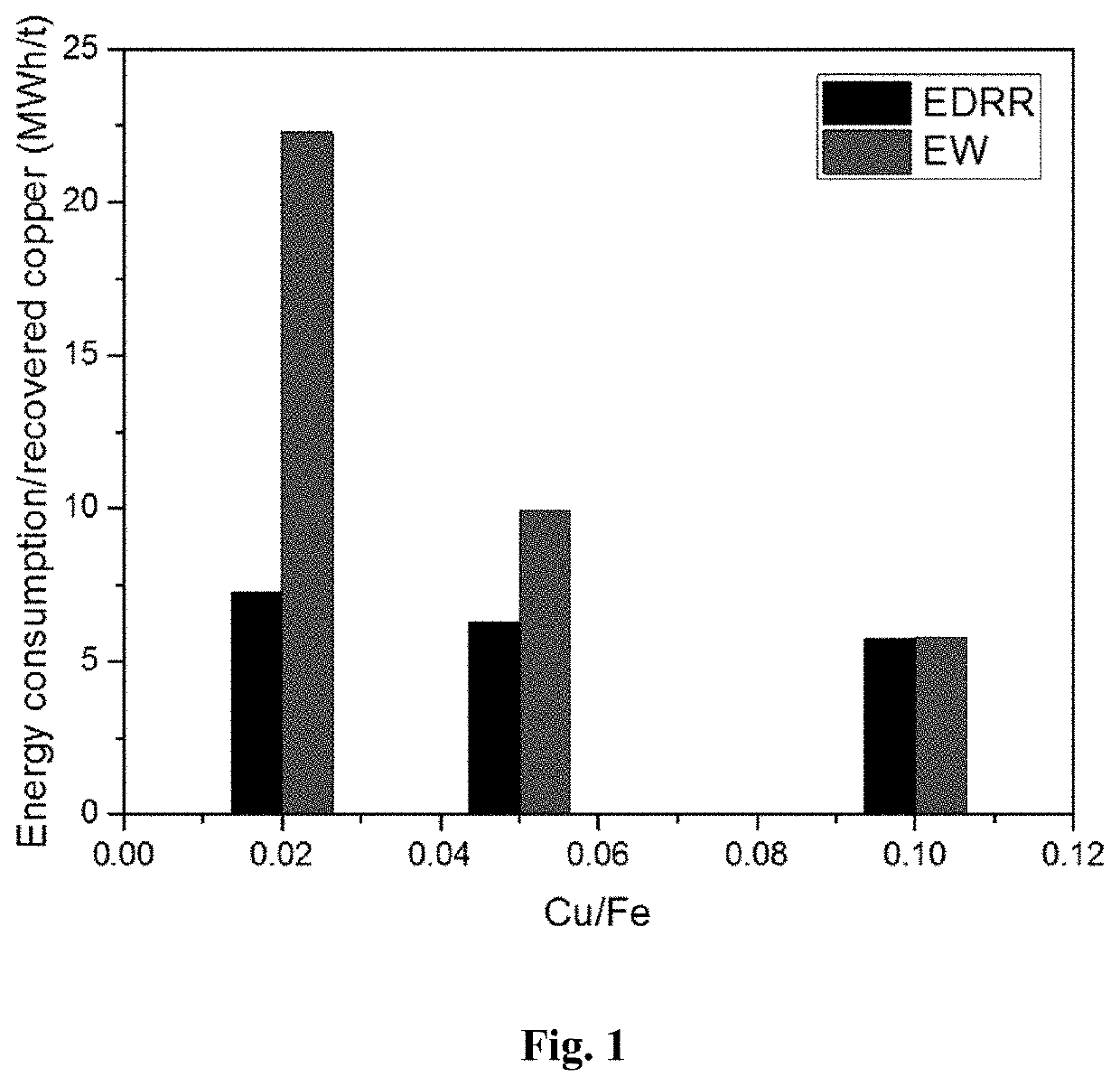
[0050]Energy consumption of the method according to the present invention (EDRR) and a traditional electrowinning method (EW) were tested in copper recovery from synthetic solutions having a Cu / Fe ratio of 0.02, 0.05 and 0.1 (copper concentration of 2, 5 or 10 ppm and Fe concentration of 100 ppm).

[0051]Recovery of copper on stainless steel working electrode (area 16 cm2) was performed in 2000 ml of solution (solution parameters: [Fe]=100 mg / L, [Cu]=1-10 mg / L, [H2SO4]=10 g / L, pH=1), with magnetic stirring at 400 rpm. A standard calomel electrode (SCE) was acting as a reference electrode (RE) and stainless steel as a counter electrode (CE).

[0052]Solution samples were taken at the following time points: before, 1, 5, 10, 20, 30, and 60 min, and the amount of copper was detected by ICP. In EDRR, the potential applied to the electrode during the electrodeposition (ED) step was −0.55 V vs. SCE (Edeposition=−0.55 V vs. SCE), the deposition time was 10 s, the cut-off potential for ...

example 2

f the Product (Tests from Synthetic Mine Waters and from a Real Mining Water)

[0059]The method was tested in synthetic solutions with additional impurities (e.g. Zn, Al, Pb), i.e. mimicking real mine waters. The composition of 10 g / l H2SO4 solutions is shown in Table 3, together with the achieved product quality (Cu / Fe) after applying EDRR method in each synthetic mine water solution. The product quality was determined by SEM-EDX analysis from Pt working electrode after 10 EDRR cycles (EED=−0.45 V vs. SCE for Solutions 1 & 2 and EED=−0.50 V vs. SCE for Solution 3, time of the step=10 s for each solution, Ecut-off=0.30 V vs. SCE for each solution) while using Pt sheet as working electrode (0.4 cm2), Pt sheet as counter electrode and standard calomel electrode (SCE) as reference electrode.

[0060]

TABLE 3Synthetic mine waters and achievedproduct quality from SEM analysisProduct QualitySolution[Cu][Fe][Zn][Al][Pb]from SEMComposition(ppm)(ppm)(ppm)(ppm)(ppm)(Cu / Fe)Solution 1100400080——1.9So...

example 3

Cycling Between the Steps

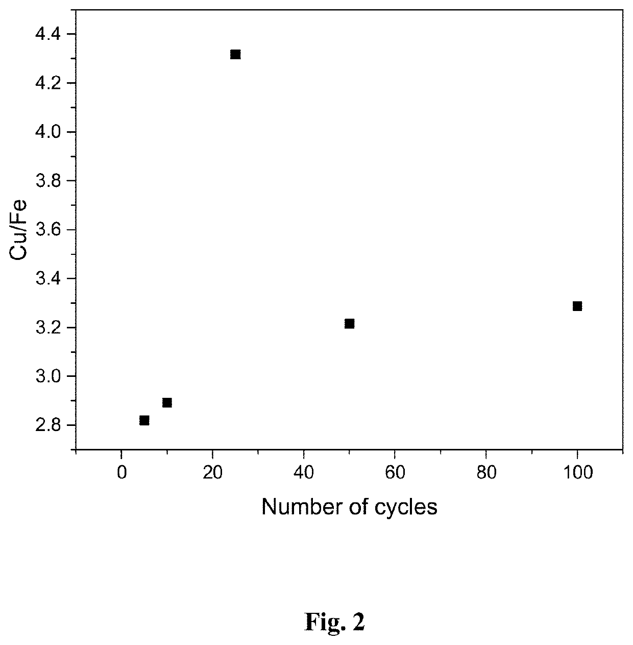
[0064]The effect of cycling on the quality of the product was investigated in a synthetic solution ([Cu]=100 mg / L, [Fe]=4 g / dm3, pH=1.2, [H2SO4]=10 g / L). The chemicals used for preparing the solution were FeSO4.7H2O, CuSO4.5H2O and concentrated H2SO4. Electrodeposition potential was −0.60 V vs. SCE, deposition time 10 s, and cut-off potential for redox replacement step +0.25 V vs. SCE. The working electrode was Pt sheet (0.4 cm2 area), counter electrode was Pt sheet and reference electrode a standard calomel electrode (SCE).

[0065]The results in FIG. 2 show that the quality of copper product (shown as Cu / Fe ratio) is not effected by the number of cycles, but the copper concentration is approximately three times higher compared to iron regardless of the number of cycles.


PUM

PropertyMeasurementUnit
Fractionaaaaaaaaaa
Fractionaaaaaaaaaa
Fractionaaaaaaaaaa

Abstract

The invention relates to a method of removing and / or recovering metals from a dilute metal containing solution. In particular, the invention concerns a method for recovering copper from a dilute copper-iron bearing mining water, particularly from a copper-iron bearing mining wastewater.

Description

FIELD OF THE INVENTION[0001]The field of the invention relates to a method of removing and / or recovering metals from a dilute metal containing solution. In particular, the invention concerns a method for recovering copper from a dilute copper-iron bearing mining water, particularly from a copper-iron bearing mining wastewater.BACKGROUND OF THE INVENTION[0002]Wastewater from abandoned sulphide mines is considered as harmful waste for the environment. Mines containing sulphidic minerals end up suffering from acidic metal containing waters with time, when minerals or ore body are exposed to air and water. Several mine waters need to be treated in order to prevent metal(s) ending up to nature as acid drainage or bleed water, potentially killing aquatic animals and plants. In the USA, 5-10% of the abandoned mines are considered to be health and safety hazards and 1-2% to present an environmental risk due to water pollution. Also in developing countries the regulation is getting stricter,...

Claims


Application Information

Patent Timeline
IPC IPC(8): C02F1/70C02F1/461C25C1/12C25C1/06C25C1/20C02F103/10C02F101/20
CPCC02F1/705C02F1/46109C25C1/06C25C1/12C25C1/20C02F2001/46138C02F2001/46152C02F2101/20C02F2103/10C22B15/0091Y02P10/20C02F1/461C02F1/70
Inventor LUNDSTRÖM, MARIYLINIEMI, KIRSI
Owner ELMERY OY
Learn More