
Method for joining at least two structural parts

a structural part and jointing technology, applied in the direction of threaded fasteners, screwdrivers, manufacturing tools, etc., can solve the problems of increased gap, increased manufacturing costs, and increased manufacturing costs, so as to reduce the visibility of rivets, reduce the effect of die gravure and expand the range of applications

Active Publication Date: 2021-01-12
AUDI AG
View PDF21 Cites 0 Cited by
  • Summary
  • Abstract
  • Description
  • Claims
  • Application Information

AI Technical Summary

Benefits of technology

This patent describes an auxiliary joining element that is used to join aluminum and steel components. The element is designed to improve welding results by using a defined head projection and displacing glue. The element is made of a specific steel material that can be cold-upet or cold-extruded, which offers economic manufacturing. The geometry and coating of the element are also important factors for ensuring good welding. The element has a ring contour to prevent premature deformation and can be pressed into the first component using a flat die or a die with small graver. The auxiliary joining element helps to expand the range of applications for riveting and can be used in various industries such as automotive, aerospace, and energy.

Problems solved by technology

In ultra-high-strength steels the semi-hollow punch riveting does not offer a sufficient joining quality due to the very high material strengths of the steel.
For example the rivet may be damaged or may not be sufficiently formed.
The above-stated conventional joining methods, i.e., the semi-hollow punch riveting or resistance element welding, have several drawbacks and limitations: for example the element head of the auxiliary joining element remains visible also after completion of the joining connection and protrudes with a head projection over the component surface.
In addition a gap may form between the element head of the auxiliary joining element and the component contacting it, which gap may become greater under the influence of mechanical stress and corrosive media may enter through the gap.
As a result of a potentially present offset or an eccentric contact of the welding electrodes on the auxiliary joining element the direction of current flow changes which may lead to a shunt between the semi-finished steel product and the semi-finished aluminum product.
As a result insufficient heat is available for the formation of a weld nugget, which may lead to a reduced connection formation.

Method used


Image

  • Method for joining at least two structural parts
  • Method for joining at least two structural parts
  • Method for joining at least two structural parts

Examples


Embodiment Construction

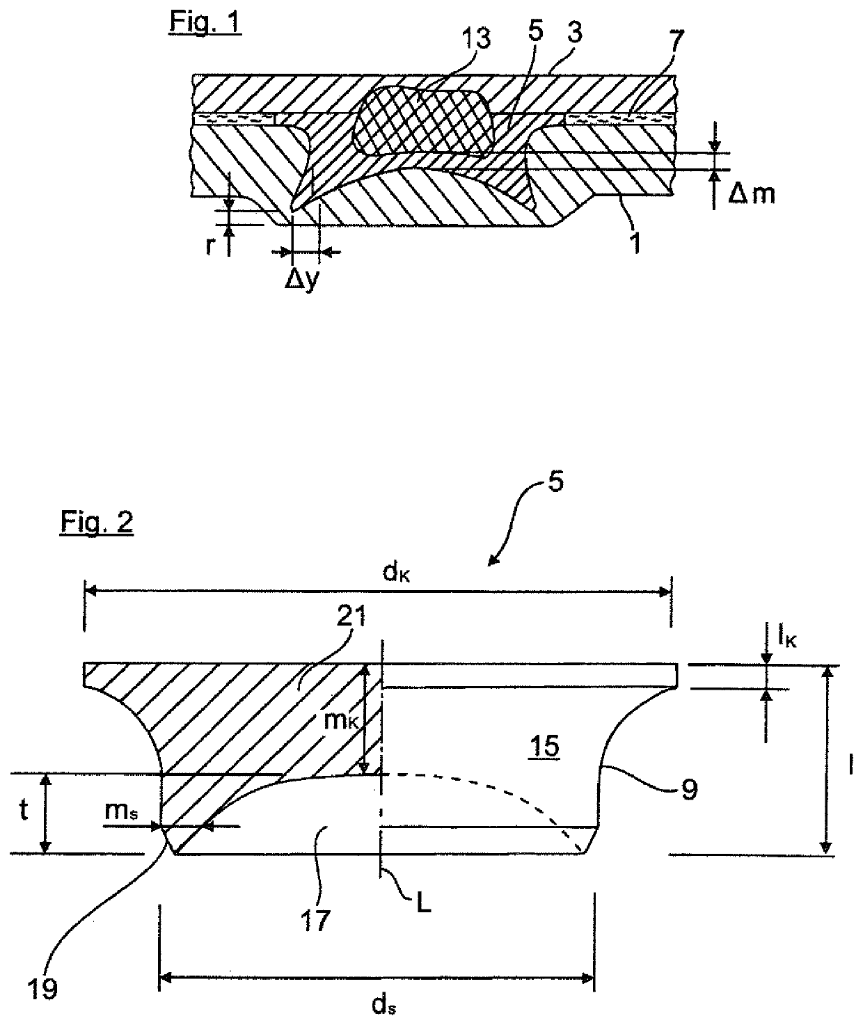
[0033]FIG. 1 shows a finished component connection in which an aluminum sheet as a first joining partner is connected with a steel sheet 3 as a second joining partner. The two joining partners 1, 3 are connected with each other via an auxiliary joining element 5. In addition an adhesive layer 7 is provided between the joining partners 1, 3. The above material pairing is purely exemplary. As an alternative also any other materials are conceivable, for example magnesium and potentially also plastic materials.

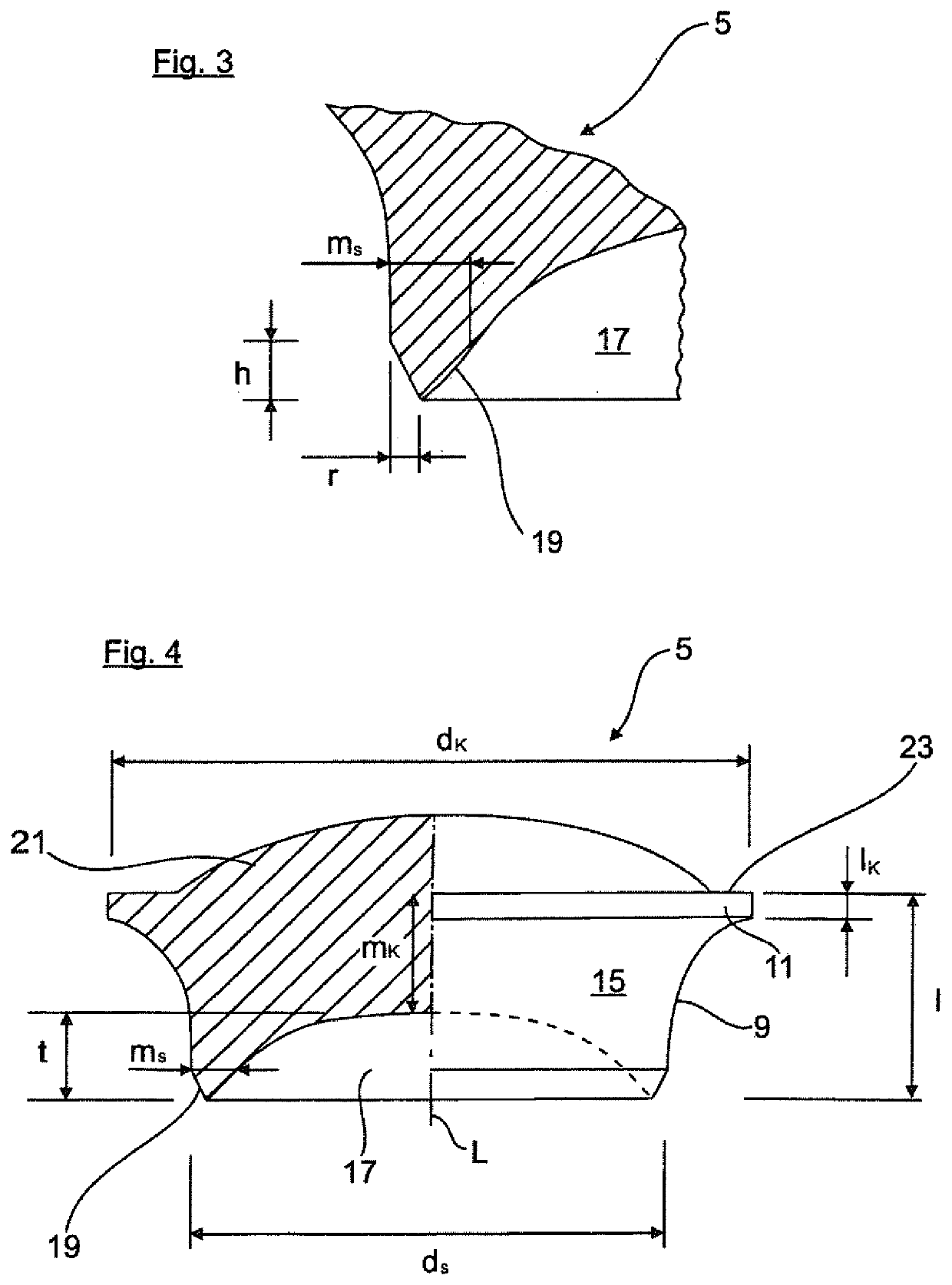
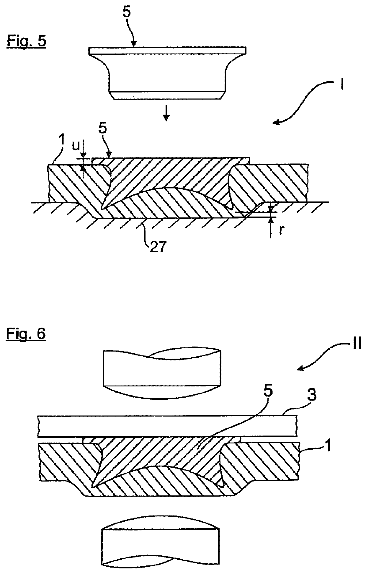
[0034]According to the figures the auxiliary joining element 5 is formed with a hollow element shaft 9 and an element head 11. In FIG. 1 the element shaft 9 is driven into the material of the aluminum sheet (first joining partner) 1 in a setting step I described below while maintaining a residual material thickness r. The element head 11 of the auxiliary joining element 5 on the other hand is welded with the second component (steel sheet part) 3 so as to form a weld nugget 13.

[003...


PUM

PropertyMeasurementUnit
thicknessaaaaaaaaaa
thicknessaaaaaaaaaa
diameteraaaaaaaaaa

Abstract

A method for joining at least two structural parts includes a fitting step in which a joining element is driven into the first structural part while a residual material thickness is maintained, and a joining step in which the joining element driven into the first structural part is connected to the second structural part. The joining element has a hollow element shaft, which is driven into the first structural part, and an element head, which is welded or adhesively bonded to the second structural part.

Description

CROSS-REFERENCES TO RELATED APPLICATIONS[0001]This application is the U.S. National Stage of International Application No. PCT / EP2015 / 001328, filed Jul. 1, 2015, which designated the United States and has been published as International Publication No. WO 2016 / 020025 and which claims the priority of German Patent Application, Serial No. 10 2014 011 599.2, filed Aug. 2, 2014, pursuant to 35 U.S.C. 119(a)-(d).BACKGROUND OF THE INVENTION[0002]The invention relates to a method for joining at least two components according to patent claim 1 and an auxiliary joining element according to patent claim 12, which can be used as an auxiliary joining element in such a method.[0003]In automobile construction the vehicle body can be manufactured in a mixed construction in which for example semi-finished aluminum parts and semi-finished steel parts are joined. The semi-finished parts can hereby preferably be connected to each other by a mechanical joining method (i.e. without change in microstruct...

Claims


Application Information

Patent Timeline
Patent Type & Authority Patents(United States)
IPC IPC(8): B23K11/11F16B5/08B23K11/20F16B5/04F16B19/08F16B33/00B21J15/00B23K103/20F16B19/04
CPCB23K11/115B21J15/00B23K11/20F16B5/04F16B5/08F16B19/086F16B33/008B23K2103/20F16B2019/045
Inventor KOTSCHOTE, CHRISTIANNEUDEL, CHRISTIANBÄR, CARSTEN
Owner AUDI AG
Learn More