Ozone generation at high pressures

a high pressure, ozone technology, applied in the direction of ozone preparation, ozone preparation, inorganic chemistry, etc., can solve the problems of inability to achieve economic ozone production and high ozone concentration at high pressure, and the inability to arbitrarily reduce the gap in this type of ozone generator, so as to achieve high ozone concentration and achieve high ozone capacity effectively

Active Publication Date: 2020-11-10
XYLEM IP MANAGEMENT SARL
View PDF18 Cites 0 Cited by
  • Summary
  • Abstract
  • Description
  • Claims
  • Application Information

AI Technical Summary

Benefits of technology

[0008]The object of the present invention is to provide a method for the production of ozone at elevated pressure in which high ozone concentrations and high ozone capacities can be achieved effectively.
[0012]The gas containing oxygen is preferably at least 80% O2 and more preferably at least 98% O2. This means high ozone concentrations can be produced with good energy efficiency.
[0013]The ozone is preferably produced with a production rate of at least 20 kg of ozone / h and in particular 100 kg of ozone / h. At this capacity, an ozone generation system of the type mentioned above is particularly effective.
[0014]It is advantageous if the gas containing oxygen flows into the gap at a feed-in rate in the range from 500 kg / h O2 to 800 kg / h O2.
[0018]It is advantageous if the fabric made of wire fills the gap.

Problems solved by technology

For production-related reasons, the gap in this type of ozone generators cannot be arbitrarily decreased to ensure operation at high pressures.
Furthermore, only power supplies of up to around 20 kV can be used due to insulation problems.
Economic ozone production and the generation of high concentrations of ozone is therefore not possible at high pressures.
Any deviations from this optimal operating pressure result in considerable reductions in efficiency (“Ozone production in a high frequency dielectric barrier discharge generator”, R. G. Haverkamp et al., Ozone Science & Engineering Vol. 24, pp 321-328).
Higher operating pressures are therefore uneconomical for conventional ozone generators.
However, these compressors are expensive to buy and consume high quantities of energy.

Method used


Image

  • Ozone generation at high pressures
  • Ozone generation at high pressures

Examples


Embodiment Construction

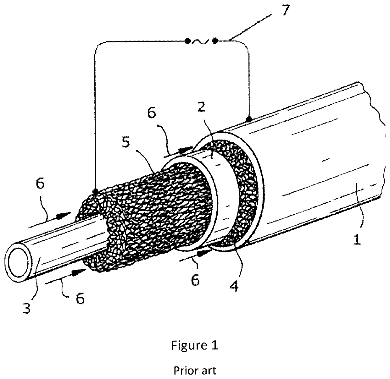
[0023]FIG. 1 shows an electrode arrangement as known from DE 10 2011 008 947 A1. Ozone generators of this type are used in an ozone generator in groups. The ozone generators are thereby arranged parallel to one another between two tube plates in the manner of a tube bundle heat exchanger and connected in an electrically parallel manner. The ozone generator shown has a tubular outer electrode 1, an also tubular dielectric 2 and an internal rod 3, wherein shortened versions of the individual components are shown stretched out from one another in an axial direction. The arrangement is rotationally symmetrical. The outer electrode 1, the dielectric 2 and the rod 3 are oriented concentrically to one another. There is a wire mesh 4 between the outer electrode 1 and the dielectric 2 that fills the gap. Accordingly, a wire mesh 5 is provided between the dielectric 2 and the rod 3 which also fills the gap there. The outer electrode 1 is designed in the form of a stainless steel tube. The was...


PUM

PropertyMeasurementUnit
voltageaaaaaaaaaa
gas pressureaaaaaaaaaa
voltageaaaaaaaaaa

Abstract

A method for producing ozone at elevated pressure with a capacity of at least 1 kg ozone / hour by an ozone generator having a high voltage electrode and a counter electrode. The electrodes delimit a gap in which a dielectric is arranged and through which a gas containing oxygen and having a gas pressure of pgas flows. The high voltage electrode and the counter electrode with a connection for an electric power supply to generate discharges are provided in at least one discharge gap. The power supply provides a voltage in a range from 1 kV to 50 kV and wherein stroke widths di of the discharge are distributed between a minimum stroke width dmin and a maximum stroke width dmax. The gas pressure pgas of the gas containing oxygen at the outlet of the ozone generator is at least 3 bar.

Description

CROSS-REFERENCE TO RELATED APPLICATIONS[0001]This patent application is a U.S. National Phase patent application of PCT Application No.: PCT / EP2017 / 052752, filed Feb. 8, 2017, which claims priority to European Patent Application No. 16156070.1, filed Feb. 17, 2016, each of which is incorporated by reference herein in its entirety.FIELD OF THE INVENTION[0002]The present invention relates to a method for producing ozone at elevated pressure.BACKGROUND OF THE INVENTION[0003]High pressures at the outlet of the ozone generator of up to 12 bar are needed in some areas of application of ozone. This includes, for example, the bleaching of paper in the paper industry. Ozone generators with ozone capacities of several kg / h at working pressures of around 1-2 bar are generally used to bleach paper.[0004]The unit “bar” will be used as a technical unit of pressure in this description and claims. This is to be understood as excess pressure over atmospheric pressure. The numerical value of the abso...

Claims


Application Information

Patent Timeline
Patent Type & Authority Patents(United States)
IPC IPC(8): C01B13/11
CPCC01B13/11C01B2201/64C01B2201/22C01B2201/10
Inventor FIEKENS, RALFFIETZEK, REINERSALVERMOSER, MANFREDBRUGGEMANN, NICOLE
Owner XYLEM IP MANAGEMENT SARL
Why Eureka
Try Eureka