
Nanobubble-containing liquid solutions

a liquid solution and nano-bubble technology, applied in the field of liquid solutions, can solve the problems of inability to efficiently reduce the size of the bubble, and the system is not capable of creating the endothermic reaction required to make the fluid paramagnetic,

Active Publication Date: 2020-10-27
EBED HLDG
View PDF53 Cites 3 Cited by
  • Summary
  • Abstract
  • Description
  • Claims
  • Application Information

AI Technical Summary

Benefits of technology

The present invention provides a system and method for treating liquid solutions to destroy or reduce the growth of cells, pathogens, viruses, bacteria, fungi, spores, and molds, as well as enhance the overall quality of the source liquids. The invention involves the use of nanobubbles generated by a nanobubble generator integrated with various liquid systems, such as water heaters, water coolers, potable water systems, water sanitation systems, water softeners, ion exchangers, and the like. The nanobubble-containing liquid solutions of the invention have stable nanobubbles with a particle size of about 10 to 2000 nm that are paramagnetic and have a higher ORP relative to the source liquid. The technical effects of the invention include improved liquid quality, reduced ammonia content in manure of birds, and improved food processing, petroleum, solvents, and medical industries.

Problems solved by technology

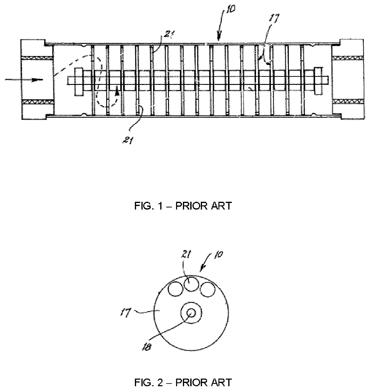
Micro-nanobubble generators currently in the market require air or a gas to produce fine bubbles and cannot efficiently reduce the size of the bubble to having a particle size of a nanometer.
All of these systems are not capable of creating the endothermic reaction required to make the fluids paramagnetic.
U.S. Pat. No. 8,317,165, for example, describes a nanobubble-containing liquid producing apparatus However, the apparatus of described in this U.S. patent can only produce nanobubbles from a microbubble base fluid and needs to utilize external gas / air to create a greater abundance of nanobubbles.

Method used


Image

  • Nanobubble-containing liquid solutions
  • Nanobubble-containing liquid solutions
  • Nanobubble-containing liquid solutions

Examples


example 1

Spin-Echo (T2) Relaxation Measurements

[0201]Spin-echo (T2) relaxation measurements were made using an Acorn Area NMR device (XiGo Nanotools, Inc., Bethlehem, Pa. 18015, USA: U.S. Pat. No. 7,417,426 Aug. 26, 2008) of untreated water and water treated with nanobubble generators. Water samples were obtained from two locations: WB and JF. Five consecutive measurements were made on each of the samples.

[0202]Table 3 illustrates the results. While the data for the two treated water samples are less reproducible than the untreated control and source samples, it is clear that the two treated samples each have a statistically valid shorter T2 relaxation time compared with their sibling control / source samples.

[0203]It was noted: (a) the random variation in the 5 consecutive measurements made on each of the two untreated (control / source) water samples and the good repeatability (low std dev and cov), and (b) the progressive increase in T2 value for the 5 consecutive measurements made on each of...

example 2

Nanoparticle Tracking Analysis of Water Treated with Nanobubble Generator

[0205]The water used in this analysis was sourced from one chicken farm located in southwestern Ontario.

Water Treatment

[0206]Source water is pumped from a cistern. The pump includes a first nanobubble generator. Chlorine was injected into the source water and then passed through a second nanobubble generator.

[0207]The twice treated water then enters the contact tanks where iron, manganese, sulphur, and other toxic minerals are oxidized and removed using GreensandPlus™ media filters. Hydrocarbon filters were then used to filter out oils, glyphosates and organophosphates. HYDRAcap 60 Hydranautics Membrane was used to remove endotoxins, virus and bacteria. The twice treated water then is passed through a third nanobubble generator. Samples were collected from the pumped source water (i.e treated once through a nanobubble generator; referred to as “Raw” sample in FIGS. 6 and 7) and from the trice treated water (ref...

example 3

Conclusion for Examples 1 and 2

[0221]The systems and methods of the present invention result in nano-bubble-containing liquid solutions with improved physical, chemical and biological properties. The nanobubble generator results in a level of shear and eddy currents that produces a defined cavitation. This cavitation then creates a pressure differential sufficient to reach a critical, threshold activation energy. It is in exceeding this threshold energy level that the creation of nano-bubbles becomes effected. This is the crux of the present methodology that distinguishes it from traditional ultrasound, homogenizers, static mixers and the like.

[0222]The nano-bubbles of the present invention are paramagnetic. Indeed, the existence of paramagnetic nano-bubbles has been confirmed using nuclear magnetic resonance (NMR) spin-echo relaxation time measurements (see Table 3).

[0223]The nano-bubbles of the present invention, being between 50-100 nanometers and paramagnetic, change completely ...


PUM

PropertyMeasurementUnit
mean sizeaaaaaaaaaa
mode sizeaaaaaaaaaa
mean particle sizeaaaaaaaaaa

Abstract

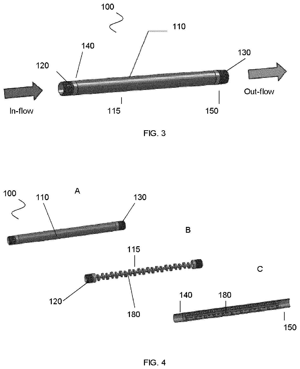
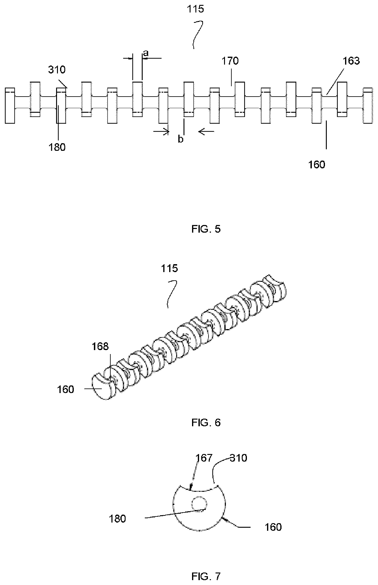
A nanobubble generator, a nanobubble-containing liquid solution comprising a substantially high concentration of nanobubbles, a system and methods of producing the nanobubble-containing liquid solution. The nanobubble generator includes an inflow portion for receiving a source liquid solution, a series of at least two sequential cavitation zones and shear planes to treat the source liquid solution and producing nano-bubble containing liquid solution, and an outflow portion for releasing the nanobubble-containing liquid solution.

Description

CROSS REFERENCE TO RELATED APPLICATIONS[0001]This application claims priority of U.S. Provisional Ser. No. 61 / 886,318, filed Oct. 3, 2013, the contents of which are hereby incorporated by reference into the present disclosure.FIELD OF THE INVENTION[0002]The present invention relates to liquid solutions having nanobubbles and to a system and a method of producing nanobubble-containing liquid solutions.BACKGROUND OF THE INVENTION[0003]In recent years, gas-liquid mixture fluid containing fine bubbles (millimeter, micrometer and nanometer size bubbles) are being used in various industries and fields of applications.[0004]Micro-nanobubble generators currently in the market require air or a gas to produce fine bubbles and cannot efficiently reduce the size of the bubble to having a particle size of a nanometer.[0005]Many generators can only produce nanobubbles through micro-bubbles and utilize a swirling fluid chamber with a single shearing point, injector or Venturi to reduce the size of...

Claims


Application Information

Patent Timeline
Patent Type & Authority Patents(United States)
IPC IPC(8): A01K39/02B01F3/04B01F5/06B08B3/08B08B9/027C02F1/48C02F1/76C02F101/10C02F101/20C02F101/30C02F101/32
CPCC02F1/76B01F5/0669B01F3/04106B08B9/027A01K39/02B01F5/0608C02F1/48B08B3/08B01F2003/04858C02F2101/206C02F2101/32B01F2215/0052C02F2307/06C02F2101/203C02F2101/30C02F2101/101B01F25/4233B01F25/44161B01F23/2375B01F23/231B01F23/231262B82B3/00B01F23/20B01F25/40B01F2101/305
Inventor BAUER, WALTER JACOB
Owner EBED HLDG
Learn More