Laser brazing method and production method for lap joint member
a technology of lap joint and production method, which is applied in the direction of manufacturing tools, solvents, transportation and packaging, etc., can solve the problems of reducing bonding strength, plating defect, delay in alloying reaction, etc., and achieves the effect of improving bead appearance and bonding strength
- Summary
- Abstract
- Description
- Claims
- Application Information
AI Technical Summary
Benefits of technology
Problems solved by technology
Method used
Image
Examples
embodiment 1
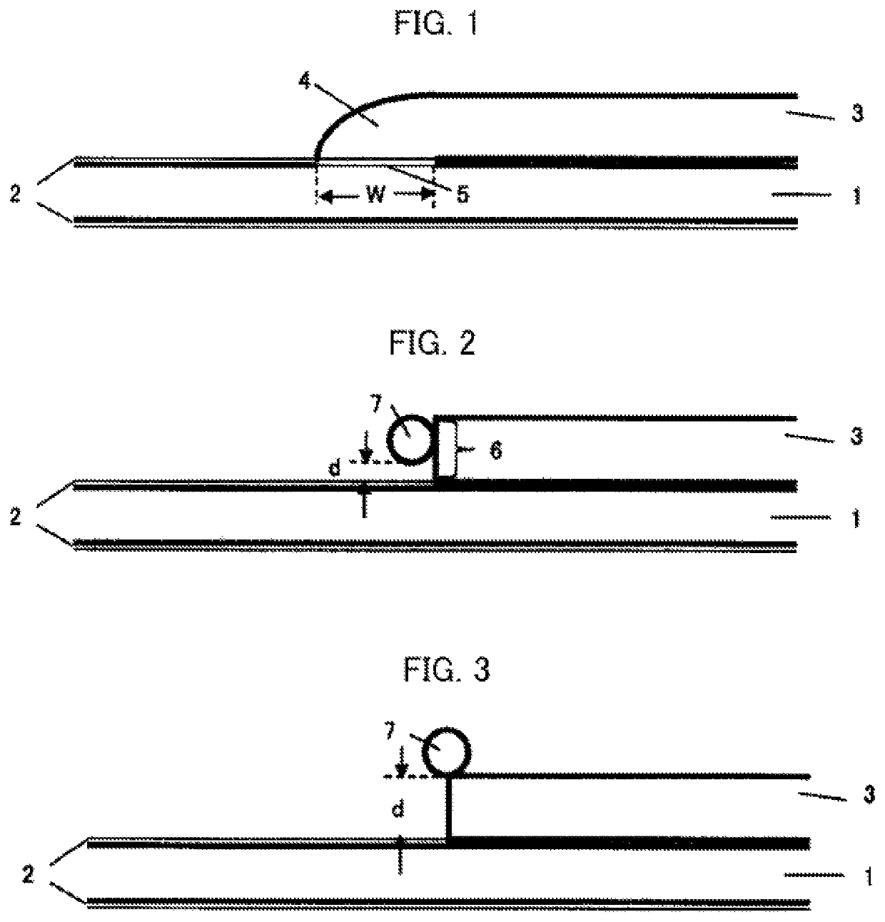
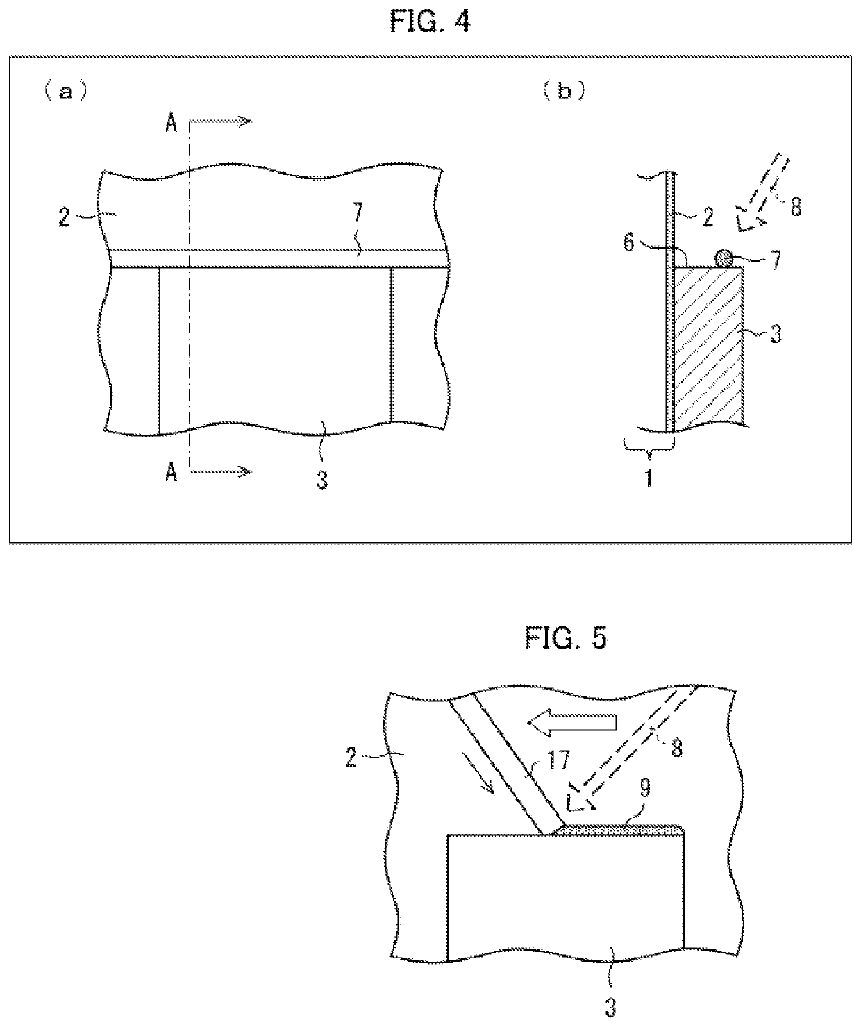
[0029]Before now, various measures have been proposed for inhibiting growth of an Fe—Al-based intermetallic compound phase in brazing. However, there are cases where the growth inhibiting effect is insufficient, and a type of steel of a coated steel sheet to which such a measure is applicable is limited. Under the circumstances, the inventors of the present invention carried out the diligent study and, as a result, the following new conception has been obtained. That is, a hot dip Zn-based alloy coated steel sheet in which a Zn-based coating layer contains Al excels in affinity with a brazing filler metal and an Al alloy. This broadens a bead width W (later described), and it is therefore possible to increase a shear plane area of a bead. From this, the inventors of the present invention have found that it is possible to prevent a decrease in bonding strength (shear strength) of the brazed part even in a case where the Fe—Al-based intermetallic compound phase has grown thicker. Base...
example 1-1
[0077]The present invention will be described below in detail with reference to Examples and Comparative Examples. Note, however, that the present invention is not limited to such Examples.
[0078]A hot dip Zn-based alloy coated steel sheet having a sheet thickness of 1.2 mm, a width of 200 mm, and a length of 100 mm, and a 6000-series Al alloy member having a sheet thickness of 2.0 mm, a width of 200 mm, and a length of 100 mm were prepared. Then, laser brazing was carried out with respect to the Al alloy member that was stacked on the hot dip Zn-based alloy coated steel sheet with a positional displacement of 50 mm in a length direction, and thus a lap joint sample was prepared. Table 1 shows laser brazing conditions.
[0079]
TABLE 1Laser welding machineDisk laser welding machineLaser output1 to 4 kWBeam diameter5 mmBrazing filler metalAl-1.0% by mass of Si,Fluoride-based flux wire,1.2 mmϕDistance (d) between brazing filler0 to 2.5 mmmetal and hot dip Zn-based alloy coatedsteel sheetSh...
example 1-2
[0088]Laser brazing was carried out with use of a hot dip Zn-based alloy coated steel sheet and each of Al alloys of 1000-series, 3000-series, 5000-series, 6000-series, and 7000-series. Table 3 shows compositions of those Al alloys.
[0089]
TABLE 3Composition (% by mass)Type of Al alloySiFeCuMnMgCrZnTiAl1000-series0.010.020.010.010.01—0.010.01Bal.3000-series0.530.210.130.880.0540.010.010.01Bal.5000-series0.090.100.020.074.630.090.160.02Bal.6000-series0.660.330.260.080.960.180.010.01Bal.7000-series0.220.131.560.122.660.215.540.02Bal.
[0090]Specifically, a hot dip Zn-based alloy coated steel sheet having a sheet thickness of 1.2 mm, a width of 200 mm, and a length of 100 mm, and an Al alloy member of each series having a sheet thickness of 1.0 mm to 3.0 mm, a width of 200 mm, and a length of 100 mm were prepared. Then, laser brazing was carried out with respect to the Al alloy member that was stacked on the hot dip Zn-based alloy coated steel sheet with a positional displacement of 50 mm ...
PUM
| Property | Measurement | Unit |
|---|---|---|
| thickness | aaaaa | aaaaa |
| boiling point | aaaaa | aaaaa |
| distance | aaaaa | aaaaa |
Abstract
Description
Claims
Application Information
 - R&D
- Intellectual Property
- Life Sciences
- Materials
- Tech Scout
- Unparalleled Data Quality
- Higher Quality Content
- 60% Fewer Hallucinations
Browse by: Latest US Patents, China's latest patents, Technical Efficacy Thesaurus, Application Domain, Technology Topic, Popular Technical Reports.
© 2025 PatSnap. All rights reserved.Legal|Privacy policy|Modern Slavery Act Transparency Statement|Sitemap|About US| Contact US: help@patsnap.com


