Image forming apparatus
a technology of image forming apparatus and forming chamber, which is applied in the direction of electrographic process, instruments, transportation and packaging, etc., can solve the problems of unfavorable aesthetic appearance, inconvenient use, and inability to meet people passing in front of the image forming apparatus, etc., to achieve the effect of enhancing convenience and aesthetic appearan
- Summary
- Abstract
- Description
- Claims
- Application Information
AI Technical Summary
Benefits of technology
Problems solved by technology
Method used
Image
Examples
first embodiment
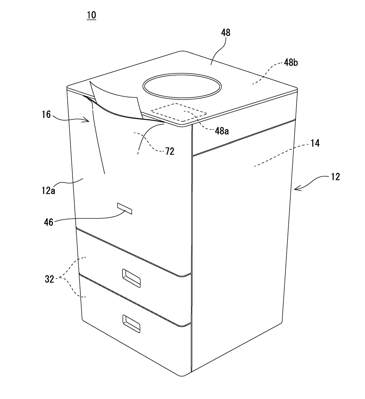
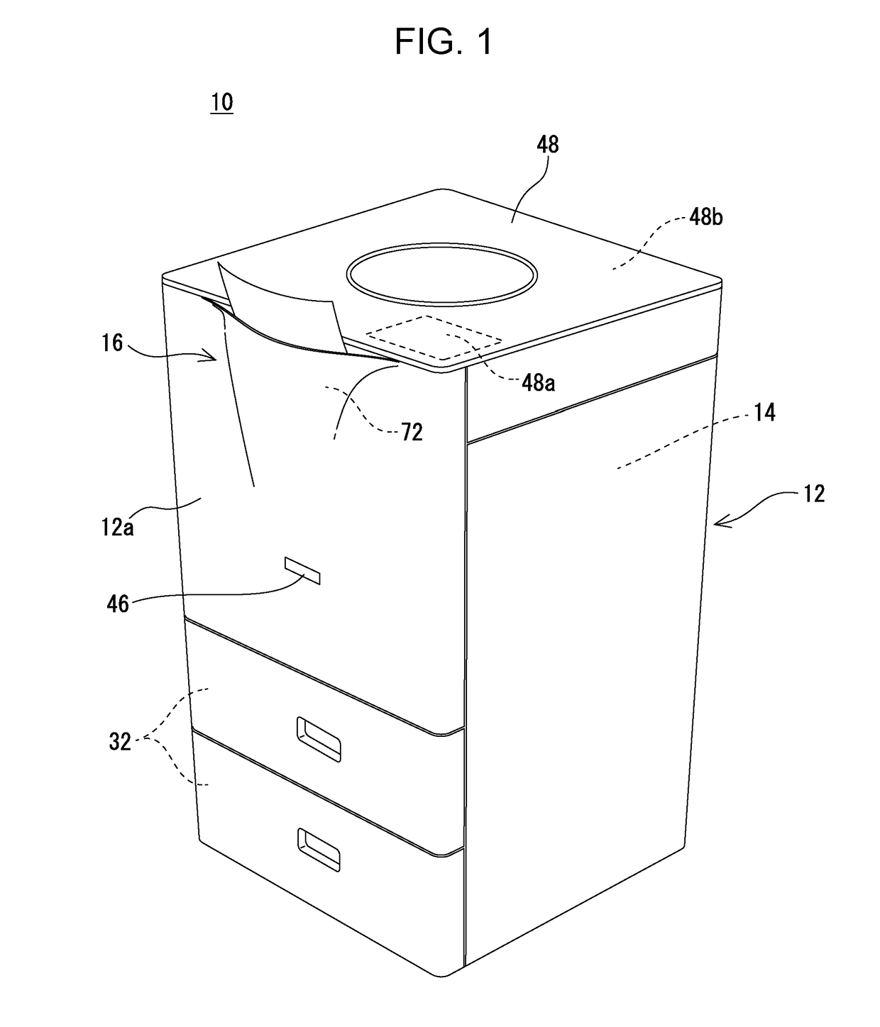
[0021]Referring to FIG. 1, an image forming apparatus 10 according to a first embodiment of the present disclosure forms a multicolor or monochromatic image on a sheet of paper (recording medium) electrophotographically and ejects, into a paper output section 16, the sheet of paper on which the image has been formed. In this first embodiment, the image forming apparatus 10 is a multifunctional printer (MFP: multifunction peripheral) having a copy function, a printer function, a scanner function, a facsimile function, and other functions.
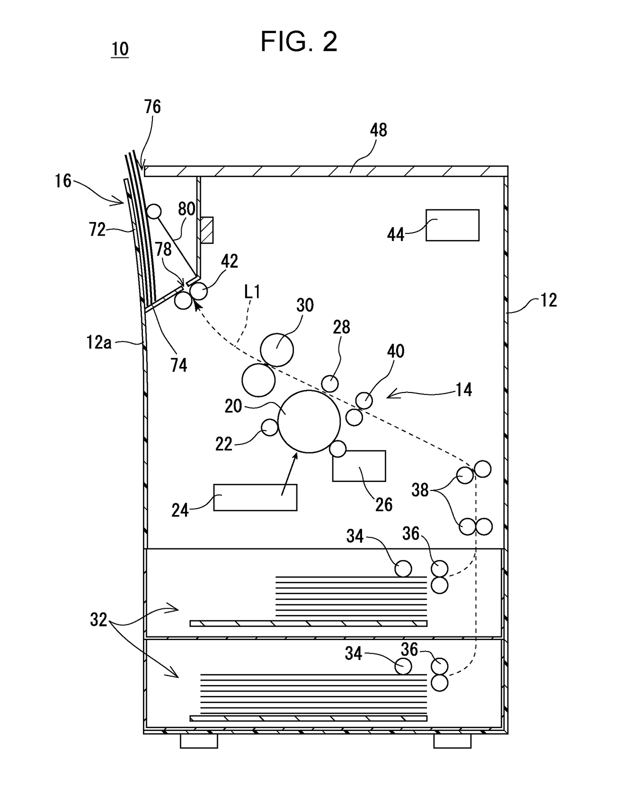
[0022]First, a basic configuration of the image forming apparatus 10 is briefly described. As shown in FIGS. 1 and 2, the image forming apparatus 10 includes a cuboidal synthetic-resin housing 12 containing an image forming section 14 and other components and, as will be described in detail later, includes, in an upper part of a front face side of the interior of the housing 12, a paper output section 16 having a paper takeout slot 76 opening upward,...
second embodiment
[0051]Next, an image forming apparatus 10 according to a second embodiment of the present disclosure is described with reference to FIGS. 7 to 10C. This second embodiment differs from the aforementioned first embodiment in that the second embodiment includes a stacking section 84. The other components of the second embodiment are identical to those of the aforementioned first embodiment. Those components of the second embodiment which are identical to those of the aforementioned first embodiment are given the same reference numerals, and a repeated description of those components is either omitted or simplified. As for the omission or the like of a repeated description, the same applies to the other embodiments described below.
[0052]In this second embodiment, the stacking section 84, in which a sheet of paper on which an image has been formed can temporarily accommodated before it is ejected into the paper output section 16, is provided below the paper output roller 42. The stacking...
third embodiment
[0061]Next, an image forming apparatus 10 according to a third embodiment of the present disclosure is described with reference to FIGS. 11 to 12B. The third embodiment differs from the aforementioned first embodiment in that the display panel 48 is movable.
[0062]In this third embodiment, the display panel 48, which constitutes the upper wall of the housing 12, is provided so as to be movable in such directions as to contact and separate from the paper output tray 72 (in this third embodiment, in front-back directions toward the front and back of the image forming apparatus 10). A usable example of a movement mechanism of the display Panel 48 is a rack-and-pinion mechanism. Simply put, the display panel 48 is provided so as to be slidable along a shaft 112 extending in the front-back directions. Racks 114 extending in the front-back directions are fixed to the right face side and left face side, respectively, of the back side of the display panel 48. A pinion gear 118 rotatably supp...
PUM
| Property | Measurement | Unit |
|---|---|---|
| angle | aaaaa | aaaaa |
| angle | aaaaa | aaaaa |
| length | aaaaa | aaaaa |
Abstract
Description
Claims
Application Information
 - R&D
- Intellectual Property
- Life Sciences
- Materials
- Tech Scout
- Unparalleled Data Quality
- Higher Quality Content
- 60% Fewer Hallucinations
Browse by: Latest US Patents, China's latest patents, Technical Efficacy Thesaurus, Application Domain, Technology Topic, Popular Technical Reports.
© 2025 PatSnap. All rights reserved.Legal|Privacy policy|Modern Slavery Act Transparency Statement|Sitemap|About US| Contact US: help@patsnap.com


