Body fluid sampling device and body fluid measuring device using the same
a body fluid and measuring device technology, applied in the field of body fluid sampling device and body fluid measuring device using the same, can solve problems such as deterioration of work efficiency and test accuracy
- Summary
- Abstract
- Description
- Claims
- Application Information
AI Technical Summary
Benefits of technology
Problems solved by technology
Method used
Image
Examples
embodiment 1
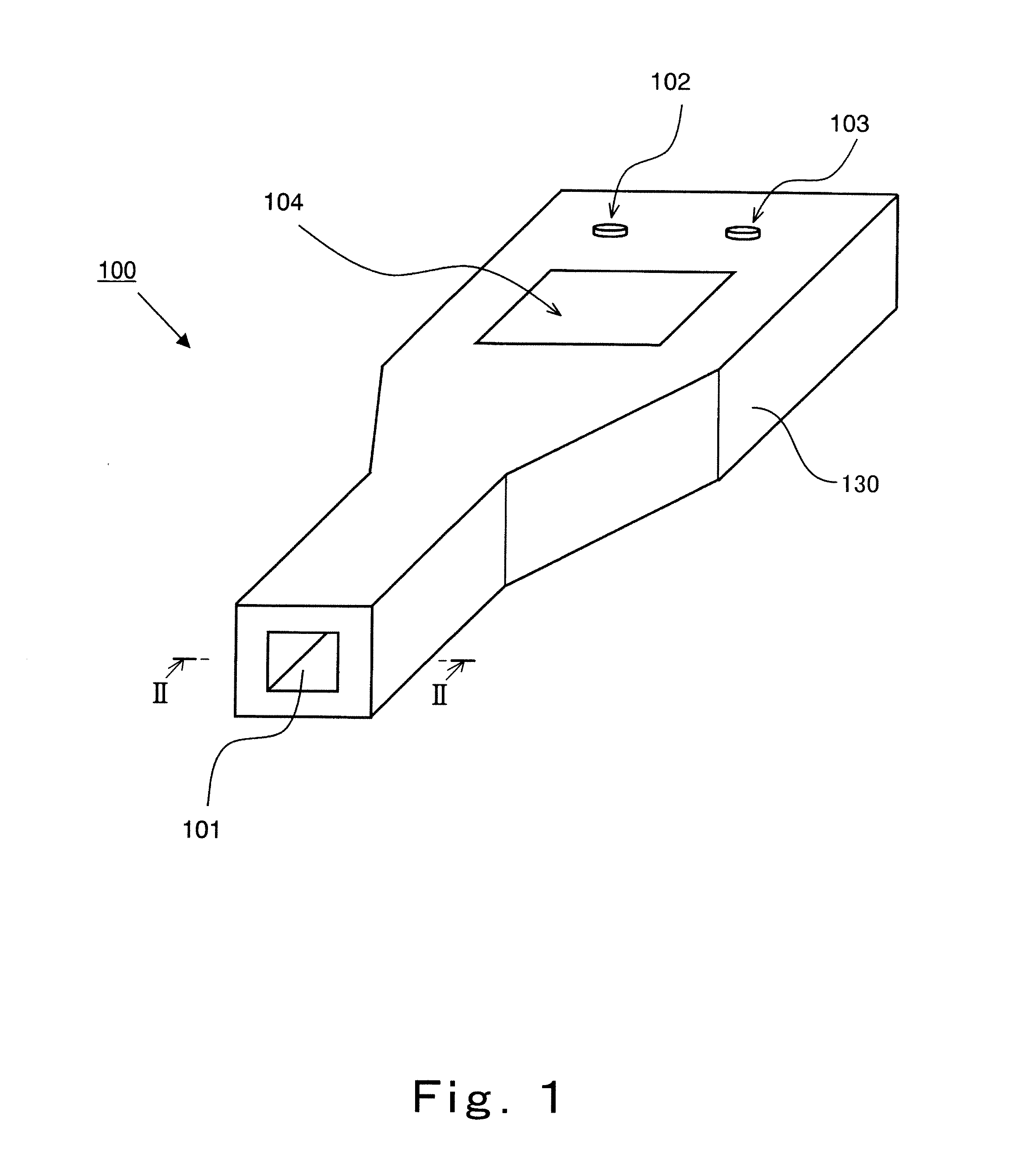
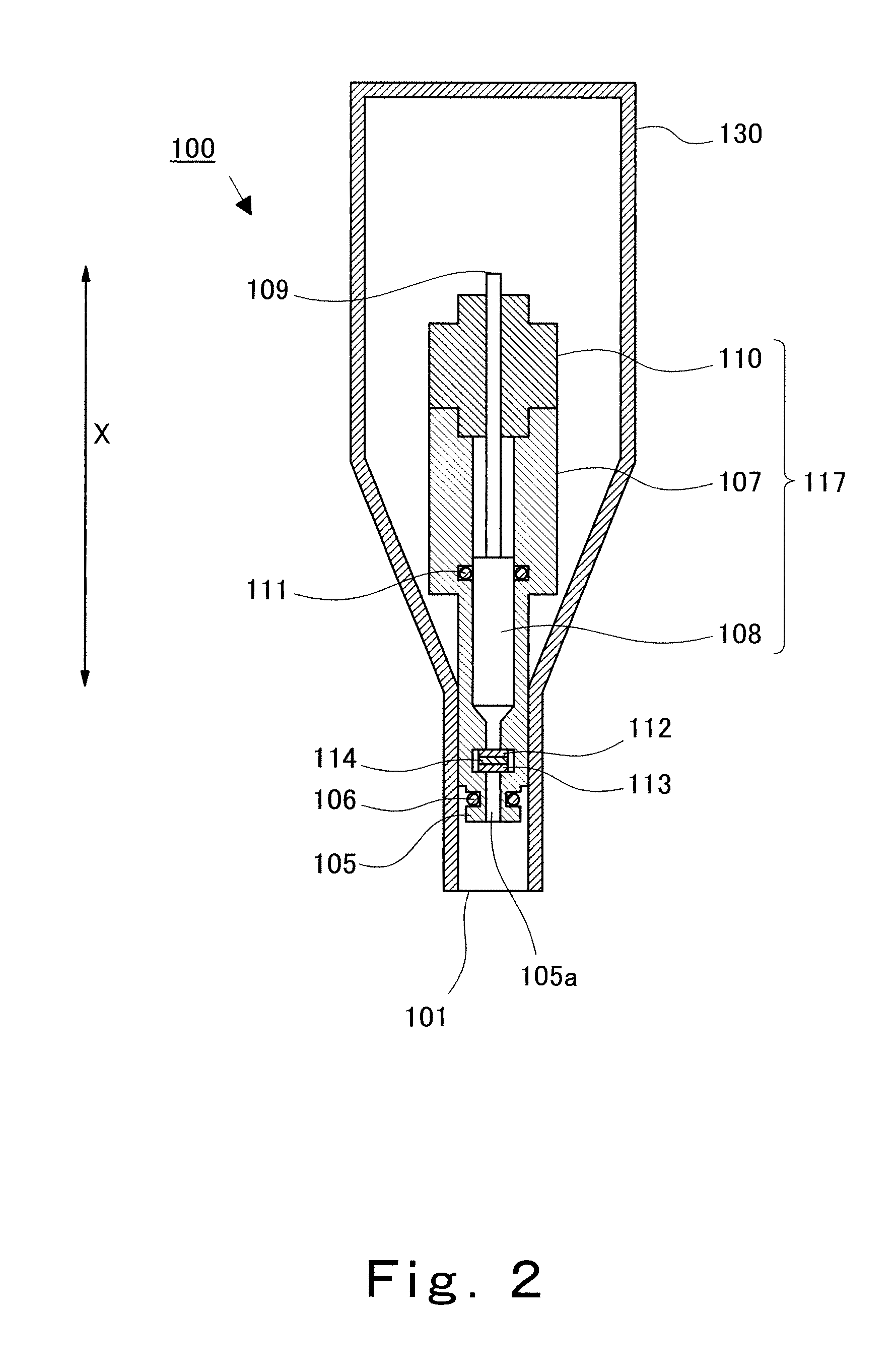
[0125]First, the configuration of a body fluid sampling device according to Embodiment 1 will be explained in reference to FIGS. 1 to 3.
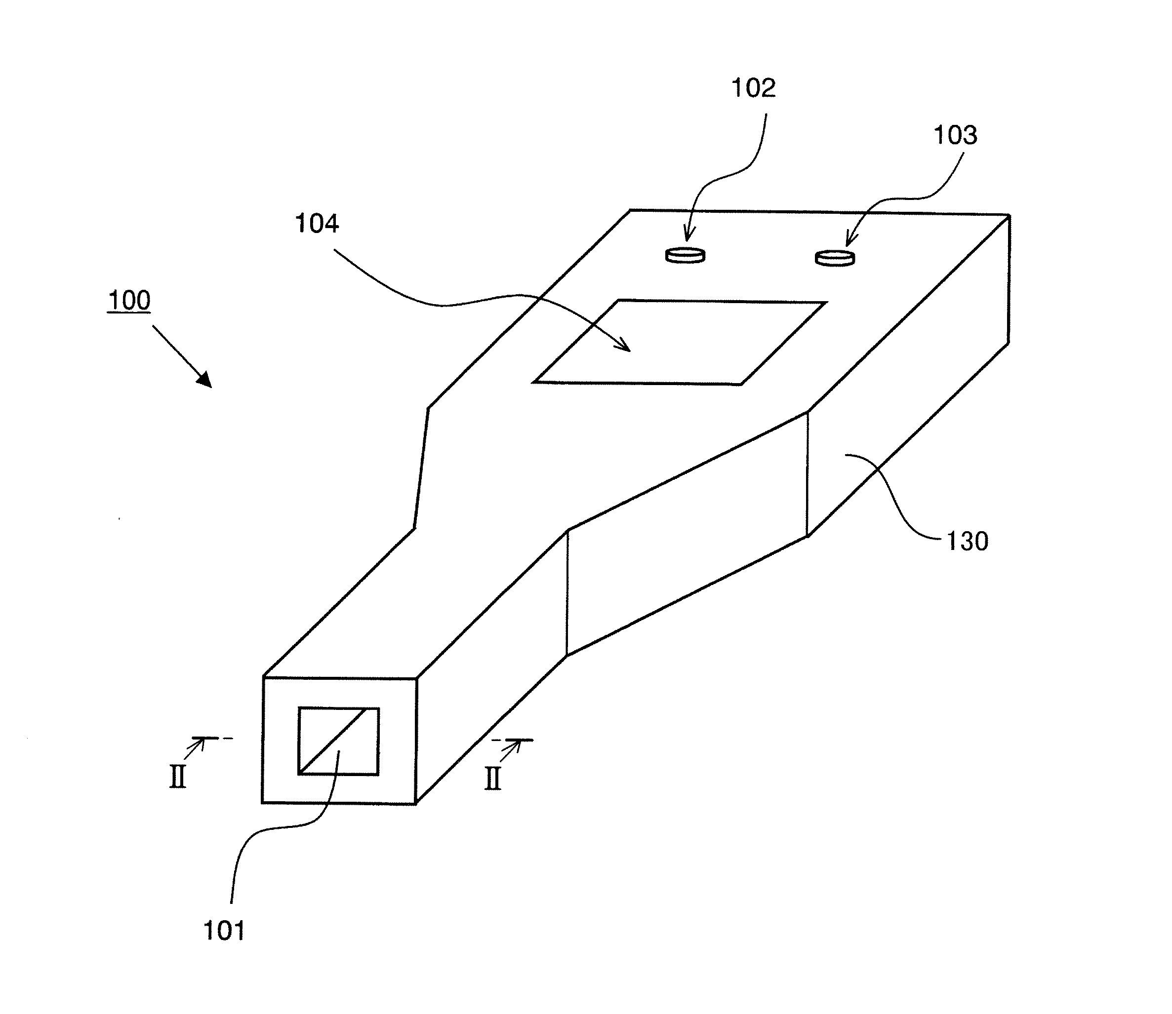
[0126]FIG. 1 is a perspective view schematically showing the configuration of an appearance of the body fluid sampling device according to Embodiment 1 of the present invention. FIG. 2 is a cross-sectional view schematically showing the configuration of a cross section of the body fluid sampling device. FIG. 3 is a block diagram schematically showing an internal configuration of the body fluid sampling device.
[0127]As shown in FIG. 1, a body fluid sampling device 100 according to the present embodiment includes a casing 130. The casing 130 includes: a body fluid container attaching portion 101 to which a body fluid container is detachably attached; a body fluid suction start button 102 by which the supply of a body fluid to the body fluid container starts; a body fluid discharge button 103 by which the body fluid in the body fluid container is disch...
embodiment 2
[0183]Next, Embodiment 2 of the present invention will be explained in reference to FIGS. 15 and 16.
[0184]FIGS. 15 and 16 are diagrams showing the portion including the body fluid container and the vicinity of the connecting portion of the body fluid sampling device according to Embodiment 2 when the body fluid container is connected to the connecting portion.
[0185]Specifically, FIG. 15 is a longitudinal sectional view schematically showing the portion including the body fluid container and the vicinity of the connecting portion of the body fluid sampling device according to Embodiment 2 when the body fluid container is connected to the connecting portion. FIG. 16 is a cross-sectional view schematically showing the configuration of a cross section taken along line G-G′ of FIG. 15. In FIGS. 15 and 16, the casing is omitted for convenience sake.
[0186]The body fluid sampling device according to Embodiment 2 is different from the body fluid sampling device according to Embodiment 1 in t...
embodiment 3
[0193]Next, Embodiment 3 of the present invention will be explained in reference to FIGS. 19 and 20.
[0194]FIGS. 19 and 20 are diagrams showing the portion including the body fluid container and the vicinity of the connecting portion of the body fluid sampling device according to Embodiment 3 when the body fluid container is connected to the connecting portion.
[0195]Specifically, FIG. 19 is a longitudinal sectional view schematically showing the portion including the body fluid container and the vicinity of the connecting portion of the body fluid sampling device according to Embodiment 3 when the body fluid container is connected to the connecting portion. FIG. 20 is a cross-sectional view schematically showing the configuration of a cross section taken along line H-H′ of FIG. 19. In FIGS. 19 and 20, the casing is omitted for convenience sake.
[0196]The body fluid sampling device according to the present embodiment is different from the body fluid sampling device 100 according to Emb...
PUM
 Abstract
Description
Claims
Application Information
 - R&D
- Intellectual Property
- Life Sciences
- Materials
- Tech Scout
- Unparalleled Data Quality
- Higher Quality Content
- 60% Fewer Hallucinations
Browse by: Latest US Patents, China's latest patents, Technical Efficacy Thesaurus, Application Domain, Technology Topic, Popular Technical Reports.
© 2025 PatSnap. All rights reserved.Legal|Privacy policy|Modern Slavery Act Transparency Statement|Sitemap|About US| Contact US: help@patsnap.com


