Combustion apparatus

a combustion apparatus and combustion plate technology, applied in the direction of combustion types, lighting and heating apparatus, fluid heaters, etc., can solve the problems of high temperature of the combustion plate flange part, high heat resistance of the packing to be used, etc., and achieve the effect of shortening the time to the ignition

Active Publication Date: 2020-09-08
RINNAI CORP
View PDF12 Cites 2 Cited by
  • Summary
  • Abstract
  • Description
  • Claims
  • Application Information

AI Technical Summary

Benefits of technology

[0006]Since the air-fuel mixture within the burner body passes through the distribution plate, the distribution plate is cooled by the air-fuel mixture. Then, according to this invention, since the distribution plate flange part comes into direct contact with the combustion plate flange part, the temperature in the combustion plate flange part lowers due to heat dissipation from the combustion plate flange part to the distribution plate. As a result, an inexpensive packing having a relatively low heat-resisting temperature as a packing comes to be made available.
[0007]In this invention, preferably the combustion plate is formed into a drawn shape (i.e., by a drawing process) having a recessed part which is depressed toward the combustion box side relative to the combustion plate flange part such that the air-fuel mixture ejection part is disposed in a bottom surface of the recessed part. The distribution plate is also preferably formed into a drawn shape having a recessed part which is depressed toward the combustion box side relative to the distribution plate flange part such that the air-fuel mixture distribution holes are formed at the bottom surface of the recessed part and that the recessed part of the distribution plate is inserted into an inside of the recessed part of the combustion plate. For the purpose of cleaning the air-fuel mixture ejection part, it is necessary to arrange the distribution plate to be detachable. As described above, by arranging such that the recessed part of the distribution plate is inserted into the inside of the recessed part of the combustion plate, the distribution plate can be easily fixed in position relative to the combustion plate, thereby improving the ease of maintenance.
[0009]In this invention, in case there is provided an ignition plug which is inserted into the combustion box in a manner to face a part of the air-fuel mixture ejection part, wherein the diameter of distribution holes formed in that portion to face the air-fuel mixture ejection part which is made to face the ignition plug is larger than the diameter of the distribution holes formed in other portions. According to this arrangement, the air-fuel mixture is quickly ejected out of the portion of the air-fuel mixture ejection part to which the ignition plug is caused to face, thereby shortening the time to the ignition.

Problems solved by technology

However, since the combustion plate becomes considerably high in temperature during combustion, the temperature of the combustion plate flange part becomes high even in the above-mentioned construction.
Therefore, the packing to be used must be of an expensive one with a high heat-resistance.

Method used


Image

  • Combustion apparatus
  • Combustion apparatus
  • Combustion apparatus

Examples


Embodiment Construction

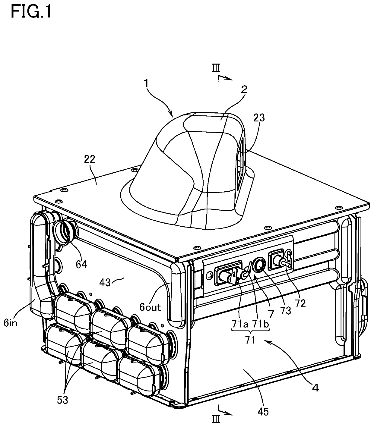
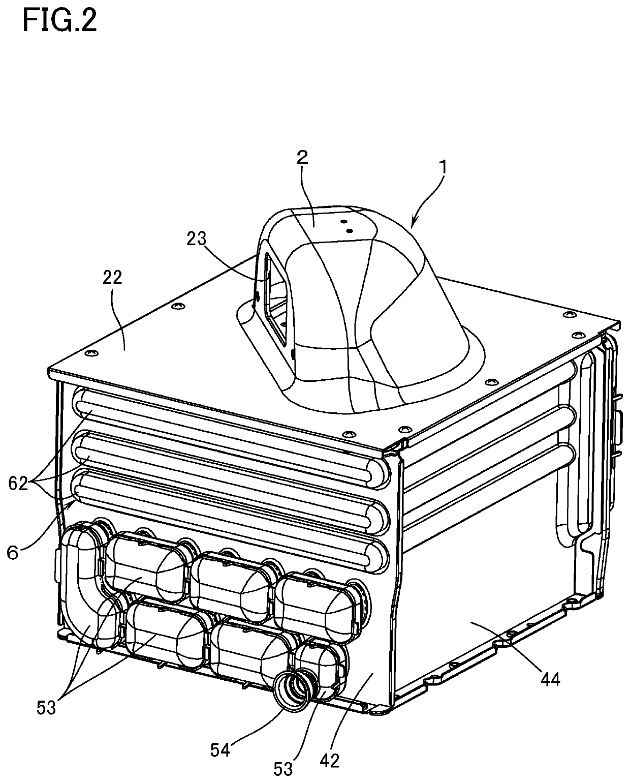
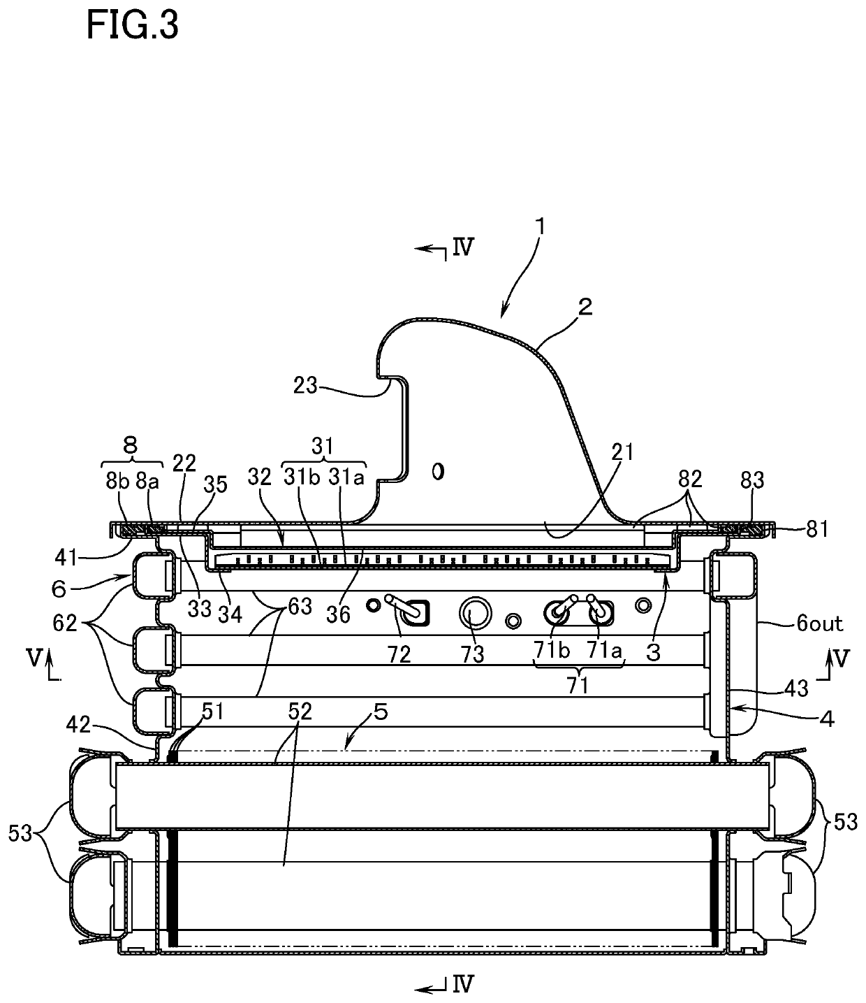
[0017]With reference to FIGS. 1 to 4, a combustion apparatus according to an embodiment of this invention is provided with: a burner 1 made up of a burner body 2 which is supplied inside thereof with air-fuel mixture (mixture gas of fuel gas and primary air); and a combustion plate 3, made of a sheet metal and having an air-fuel mixture ejection part 31, the combustion plate 3 covering a downward open surface 21 of the burner body 2; and a combustion box 4 of a sheet-metal make which has, on a perimeter of an upper end, a combustion box flange part 41 to be connected to a body flange part 22 which encloses the open surface 21 of the burner body 2. The combustion box 4 contains, inside thereof, a heat exchanger 5 for supplying hot water.

[0018]On a side surface of the portion swollen upward in the central part of the burner body 2, there is provided an inlet port 23 to which is connected a fan (not illustrated) for supplying air-fuel mixture. The combustion plate 3 has a large opening...


PUM


Abstract

A combustion apparatus has a burner including a burner body and a combustion plate, as well as a combustion box. A combustion plate flange part projects outward beyond an inner rim of a body flange part and beyond an inner rim of a combustion box flange part. A packing has a portion interposed between the combustion plate flange part and the body flange part, and a portion interposed between the combustion box flange part and the body flange part outside an outer rim of the combustion plate flange part. A distribution plate having formed therein a multiplicity of distribution holes for introducing the air-fuel mixture toward an air-fuel mixture ejection part is provided with a distribution plate flange part so arranged as to come into direct contact with that portion of the combustion plate flange part which is positioned inside an inner rim of the packing.

Description

TECHNICAL FIELD[0001]The present invention relates to a combustion apparatus comprising: a burner made up of a burner body which is supplied therein with air-fuel mixture, and a combustion plate which covers an open surface of the burner body and which has an air-fuel mixture ejection part; and a combustion box which has, on a perimeter of one end, a combustion box flange part, adapted to be connected to a body flange part enclosing the open surface of the burner body, the combustion box containing therein a heat exchanger.BACKGROUND ART[0002]As this kind of combustion apparatus, there is known an apparatus in JP-A 2017-78542 having the following features. In other words, the combustion apparatus includes: a combustion plate flange part disposed on a perimeter of the combustion plate in a manner to project outward beyond an inner rim of the body flange part and beyond an inner rim of the combustion box flange part, and also in a manner that an outer rim of the combustion plate flang...

Claims


Application Information

Patent Timeline
Patent Type & Authority Patents(United States)
IPC IPC(8): F23D14/14F24H9/02F23D14/64F23D14/02F24H1/14F28F1/14F23D14/56F24H9/18
CPCF23D14/64F24H9/1836F23D14/02F28F1/14F23D14/14F24H9/02F24H1/145F23D14/56F23D2203/10F23D2900/00019F23M5/00
Inventor ONO, TAKAHIRO
Owner RINNAI CORP
Why Eureka
Try Eureka