Common-path integrated low coherence interferometry system and method therefor

a low-coherence interferometry and common-path technology, applied in the field of subsurface imaging, can solve the problems of increased cancer risk, poor image resolution, x-ray imaging, etc., and achieve the effect of improving performan

Active Publication Date: 2020-08-25
ACADEMISCH MEDISCH CENT BIJ DE UNIV VAN
View PDF16 Cites 0 Cited by
  • Summary
  • Abstract
  • Description
  • Claims
  • Application Information

AI Technical Summary

Benefits of technology

[0013]The present invention enables low-cost, compact, integrated sub-surface imaging systems having improved performance over sub-surface imaging systems known in the prior art. Embodiments of the present invention are particularly well suited for use in low coherence interferometry applications such as optical coherence tomography, optical coherence reflectometry, optical frequency domain imaging, and the like.
[0014]Embodiments of the present invention are sub-surface imaging systems that include a common-path interferometer based on integrated-optics technology. In contrast to PLC-based interferometers of the prior-art, embodiments of the present invention are implemented without the inclusion of highly wavelength-sensitive integrated-optics components. As a result, interferometers in accordance with the present invention exhibit reduced wavelength dependence compared to PLC-based interferometers of the prior art. Further, the common-path interferometer arrangement of the present invention avoids polarization and wavelength dispersion effects that plague prior-art PLC-based interferometers based on either Michelson interferometer or Mach-Zehnder interferometers.
[0015]An illustrative embodiment of the present invention is an SD-OCT system comprising a source, a PLC-based interferometer, a scanning mirror, a reflector suitable for use as a reference surface, and a detector. The interferometer is arranged in a common-path arrangement that includes separate paths for downstream (i.e., excitation) light and upstream (i.e., back-reflected) light. As a result, there is no need for a directional coupler to split the input light into separate reference and sample arms and the reference signal and sample signal of the interferometer share a common path through the PLC. In addition, light reflected by the sample is conveyed directly to the detector by the collection waveguide, again obviating the need for a circulator or directional coupler. By avoiding the use of directional couplers and / or circulators, sensitivity to wavelength is mitigated.
[0020]In some embodiments, a PLC module includes a distribution network of surface waveguides and a collection network of surface waveguides. The distribution network provides a plurality of sample signals that collectively define a composite sample signal, such as a plane wave. The phase of each of the plurality of sample signals is controlled by a phase controller to define the shape and / or propagation direction of the composite sample signal. The composite sample signal is directed toward a region of a sample, which scatters it into scatter energy that is based on the structural features in the region. The scatter energy is coupled into the surface waveguides of the collection network as a plurality of scatter signals, which are then provided to a plurality of detector elements, each of which provides an output signal to a processor, which generates an estimate of the structure of the sample region based on the plurality of output signals. In some embodiments, the phases of the plurality of sample signals is changed multiple times to interrogate the sample region with different composite sample signals. This enables the processor to generate a compound estimate of the structural features of the sample region, thereby improving the accuracy of the estimate.

Problems solved by technology

For many years, x-ray imaging was the most widely used method of imaging sub-surface structure; however, x-ray imaging has many drawbacks—particularly in medical applications—such as poor image resolution and increased risk of cancer from large-dose and / or cumulative exposure.
Unfortunately, while early time-domain OCT techniques were promising, their complexity and time-intensive nature served to limit their widespread adoption.
Historically, the interferometer portion of most OCT systems is based on bulk optics, fiber optics, or a combination of the two, making such OCT systems relatively large and expensive.
Arrangements of surface waveguides, commonly referred to as planar lightwave circuits (PLCs), enable routing of optical signals within a small area, as well as complex optical functionality that can be difficult to achieve in free-space or fiber-optic-based systems.
This can degrade system performance and reduce signal-to-noise ratio (SNR) and / or contrast-to-noise ratio (CNR).
Further, the Michelson or Mach-Zehnder interferometer arrangements described typically exhibit large chromatic dispersion and polarization mismatches between their sample and reference arms.
While these mismatches can be compensated in optical-fiber-based interferometer systems, compensating them in a PLC-based system can be quite challenging.

Method used


Image

  • Common-path integrated low coherence interferometry system and method therefor
  • Common-path integrated low coherence interferometry system and method therefor
  • Common-path integrated low coherence interferometry system and method therefor

Examples


Embodiment Construction

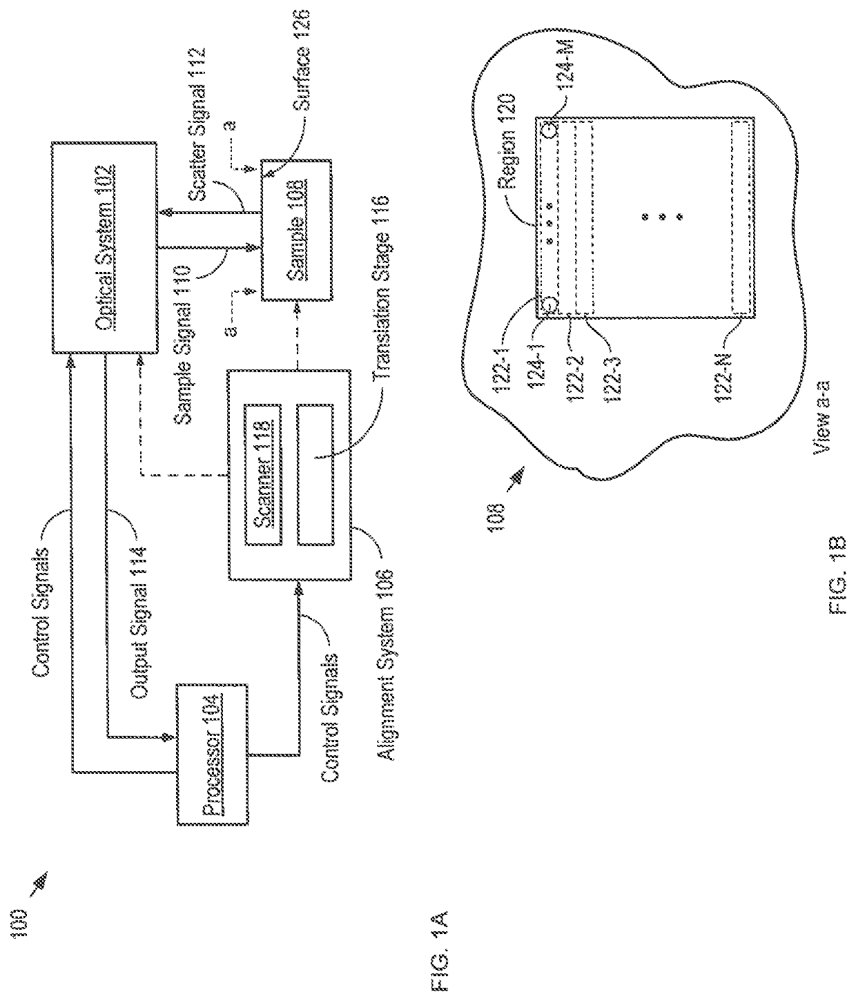
[0044]FIG. 1A depicts a schematic drawing of an imaging system in accordance with an illustrative embodiment of the present invention. System 100 is a low-coherence interferometry system comprising optical system 102, processor 104, and alignment system 106. System 100 is an OCT system that is operative for generating a three-dimensional image of the structure of a sample region.

[0045]It should be noted that low coherence interferometry (LCI) encompasses several types of imaging approaches, including optical coherence tomography (OCT), optical coherence reflectometry, partial coherence reflectometry, optical frequency domain imaging, and the like, all of which have substantially the same basic measurement set-up that includes an interferometer operated under low-coherence illumination. LCI systems have been researched and applied to different fields, including medical imaging, measuring electric or magnetic field, pressure, acceleration, fluid flow, etc., with OCT systems being the ...


PUM


Abstract

A low coherence interferometry imaging system comprising a common-path interferometer that is at least partially integrated as part of a planar lightwave circuit is disclosed. Imaging systems in accordance with the present invention are implemented in integrated optics without the inclusion of highly wavelength-sensitive components. As a result, they exhibit less wavelength dependence than PLC-based interferometers of the prior art. Further, the common-path interferometer arrangement of the present invention avoids polarization and wavelength dispersion effects that plague prior-art PLC-based interferometers. Still further, an integrated common-path interferometer is smaller and less complex than other integrated interferometers, which makes it possible to integrate multiple interferometers on a single chip, thereby enabling multi-signal systems, such as plane-wave parallel OCT systems.

Description

FIELD OF THE INVENTION[0001]The present invention relates to sub-surface imaging in general, and, more particularly, to low coherence interferometry imaging, such as optical coherence tomographic, optical frequency domain imaging, and optical coherence reflectance imaging.BACKGROUND OF THE INVENTION[0002]The ability to detect and image structure that is below the surface of a sample is desirable in many applications. For many years, x-ray imaging was the most widely used method of imaging sub-surface structure; however, x-ray imaging has many drawbacks—particularly in medical applications—such as poor image resolution and increased risk of cancer from large-dose and / or cumulative exposure. These drawbacks have fueled development of alternative sub-surface imaging methods, such as optical coherence tomography (OCT).[0003]OCT has rapidly become a critical diagnostic tool in areas such as biological, biomedical, medical screening, and vision-care. It utilizes low-coherence optical inte...

Claims


Application Information

Patent Timeline
Patent Type & Authority Patents(United States)
IPC IPC(8): G01B9/02
CPCG01B9/0209G01B9/02057G01B9/02091G01B9/02058G01B9/02051G01B9/02015
Inventor VAN LEEUWEN, ANTONIUSCOUMANS, FRANKWEISS, NICOLÁS
Owner ACADEMISCH MEDISCH CENT BIJ DE UNIV VAN
Why Eureka
Try Eureka