Process and device for dispersing gas in a liquid

a gas dispersion and liquid technology, applied in the direction of flow mixers, mixers, mixing methods, etc., to prevent the downward transmission of static pressur

Active Publication Date: 2020-03-31
SUEZ INT
View PDF23 Cites 1 Cited by
  • Summary
  • Abstract
  • Description
  • Claims
  • Application Information

AI Technical Summary

Benefits of technology

The invention aims to create a device that can mix gas and liquid without consuming too much energy or causing high liquid pressures. The device should be simple to use and maintain, and should not be affected by particles in the liquid. The device should also have sufficient air venting to prevent clogging and improve safety during operation. The pressure of the gas-liquid mixture is a function of factors such as the outlet pressure of the nozzle, pressure drops, and the weight of the column of liquid in the injection system. The invention addresses these factors to achieve a flow regime of annular liquid film type that prevents static pressure from being transmitted downwards.

Problems solved by technology

The main drawbacks are recalled below:the large pressure drop brought about in order to produce the dispersion of the gas,the limitation of the operation of these contactors to holdups of the dispersed gas phase of 30% or to gas / liquid volume ratios of 0.5 at best in the case of static mixer, submerged-jet ejector and driving-liquid Venturi ejector systems in industrial-scale applications,the limitation of the immersion height to less than a few meters at most for submerged-jet ejectors operating with gas holdups of greater than 50% corresponding to gas / liquid volume ratios of greater than 1 whereas static pressure is beneficial for gas-liquid mass transfer,the limitation of the design of the submerged jets to reduced contactor volumes and heights under the effect of probable engineering difficulties for the extrapolation of larger-scale systems,the use of structural elements such as static mixer elements, helical elements, liquid ejection nozzles that are sensitive to clogging by deposits and that require increased maintenance,operating conditions with a liquid velocity of greater than 10 m / s that are unacceptable with respect to the service life of the equipment,the poor flexibility of the systems with respect to the variation of the operating conditions.

Method used


Image

  • Process and device for dispersing gas in a liquid

Examples


Embodiment Construction

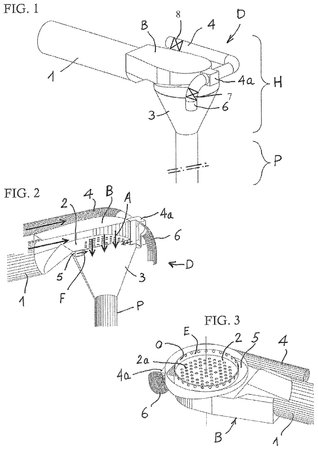
[0075]With reference to the drawing, it can be seen that the dispersion device D comprises two assemblies: an injection head H and a jet dispersion tube P, forming a nozzle. The injection head H is the structure that connects the liquid and gas inlets, mixes these fluids and directs the resulting mixture into the down tube P.

[0076]The injection head H is connected to the liquid inlet pipe 1 and comprises a compartment B with, in the lower part, a device for distributing the liquid, preferably a horizontal distribution plate 2 for the liquid, perforated with orifices 2a. The liquid flows vertically underneath the plate, following jets depicted by arrows A in FIG. 2.

[0077]An inlet line 4 for the gas to be injected is connected, via a radial box 4a, to an annular chamber 5 located under the plate 2, of which it surrounds the lower periphery. A wall E inwardly radially limiting the chamber 5 comprises nozzles or openings O for distribution of the gas following centripetal radial directi...


PUM

PropertyMeasurementUnit
Angleaaaaaaaaaa
Angleaaaaaaaaaa
Lengthaaaaaaaaaa

Abstract

Process and device for dispersing gas in a downward flow of liquid, according to which the liquid is distributed along at least one jet (A) directed downwards, preferably along a plurality of jets; gas is distributed radially (F) towards the liquid jet or jets in order to be entrained by the liquid; and the liquid-gas mixture is channeled into a downflow vertical tube (P).

Description

BACKGROUND OF THE INVENTION1. Field of the Invention[0001]The invention relates to a process and to a device for dispersing gas in a downflow of liquid.[0002]The invention relates more particularly to a hybrid mixer and jet injector gas-liquid jet dispersion process and device. The objective of the process is to homogeneously disperse the gas in the form of fine bubbles in a driving liquid for gas-liquid contacting or with a view to subsequent contacting with the bulk liquid in a surrounding contactor in which the device is implanted. The device is composed of an injection head comprising a liquid-jet mixing chamber in the upper part and a vertical coaxial tube with two-phase jet in the lower part, forming a nozzle. Said homogeneous gas-liquid dispersion is produced for a gas holdup of between 5% and 70%, preferably between 30% and 50%.[0003]The invention relates more particularly to a process and a device for injecting ozone or a mixture of ozone and oxygen and / or air into a flow o...

Claims


Application Information

Patent Timeline
IPC IPC(8): B01F3/04B01F5/04B01F5/06
CPCB01F3/04503B01F3/04751B01F5/048B01F3/0446B01F3/04106B01F5/0651B01F3/04439B01F2003/04872B01F2003/04879B01F2003/04893B01F2003/04886B01F23/2323B01F23/23412B01F23/23762B01F23/237612B01F23/237613B01F25/31423B01F25/4334B01F23/236B01F23/232B01F23/231B01F23/2319B01F23/237611
Inventor BAIG, SYLVIEFONSECA, PEDROLE QUESNE, FRANCOIS
Owner SUEZ INT
Why Eureka
Try Eureka