Control circuit and control method for controlling delay lock loop in dynamic random access memory

a dynamic random access memory and control circuit technology, applied in pulse automatic control, digital storage, instruments, etc., can solve the problems of memory performance becoming more of a limiting factor in system performance, skew between clk_b and clk_r generation, etc., to shorten the access time of the dram, and increase the number of activations

Active Publication Date: 2020-03-03
NAN YA TECH
View PDF1 Cites 0 Cited by
  • Summary
  • Abstract
  • Description
  • Claims
  • Application Information

AI Technical Summary

Benefits of technology

[0005]The present invention therefore aims to provide a control circuit and a control method for the DRAM to control the DLL, wherein when a PD detects that a READ command is received, the filter increases the number of activations for the DLL to update the delay line. The jitter in the output data is not considered until the output data is ready to be sent out, so that the skew between the calibrated clock and the reference clock can be effectively eliminated, thereby shortening the access time of the DRAM.
[0006]The present invention provides a control circuit for controlling a DLL in a DRAM, the control circuit comprising: a DLL receiving an reference clock and updating a delay line, and then outputting a calibrated clock via a clock tree; a PD receiving the calibrated clock via the clock tree and detecting a phase difference between the calibrated clock and the reference clock; and a filter activating the DLL to update the delay line according the phase difference, wherein when a READ command is received, the filter increases the number of activations for the DLL to update the delay line.
[0007]The present invention also provides a control method for controlling a DLL in a DRAM, the method comprising: receiving, by the DLL, an reference clock; updating, by the DLL, a delay line; outputting, by the DLL via a clock tree, a calibrated clock; receiving, by a PD via the clock tree, the calibrated clock outputted by the DLL; detecting, by the PD, a phase difference between the calibrated clock and a reference clock; and activating, by a filter, the DLL to update the delay line according the phase difference, wherein when a READ command is received, the filter increases the number of activations for the DLL to update the delay line.

Problems solved by technology

As CPU speeds continue to increase, memory performance becomes more of a limiting factor in system performance.
A problem occurs when a skew between the CLK_B and the CLK_R is generated because the voltage level of the clock tree 11 drops slowly during the READ operation.

Method used


Image

  • Control circuit and control method for controlling delay lock loop in dynamic random access memory
  • Control circuit and control method for controlling delay lock loop in dynamic random access memory
  • Control circuit and control method for controlling delay lock loop in dynamic random access memory

Examples


Embodiment Construction

[0017]The decryption is made for the purpose of illustrating the general principles of the present invention and should not be taken in a limiting sense.

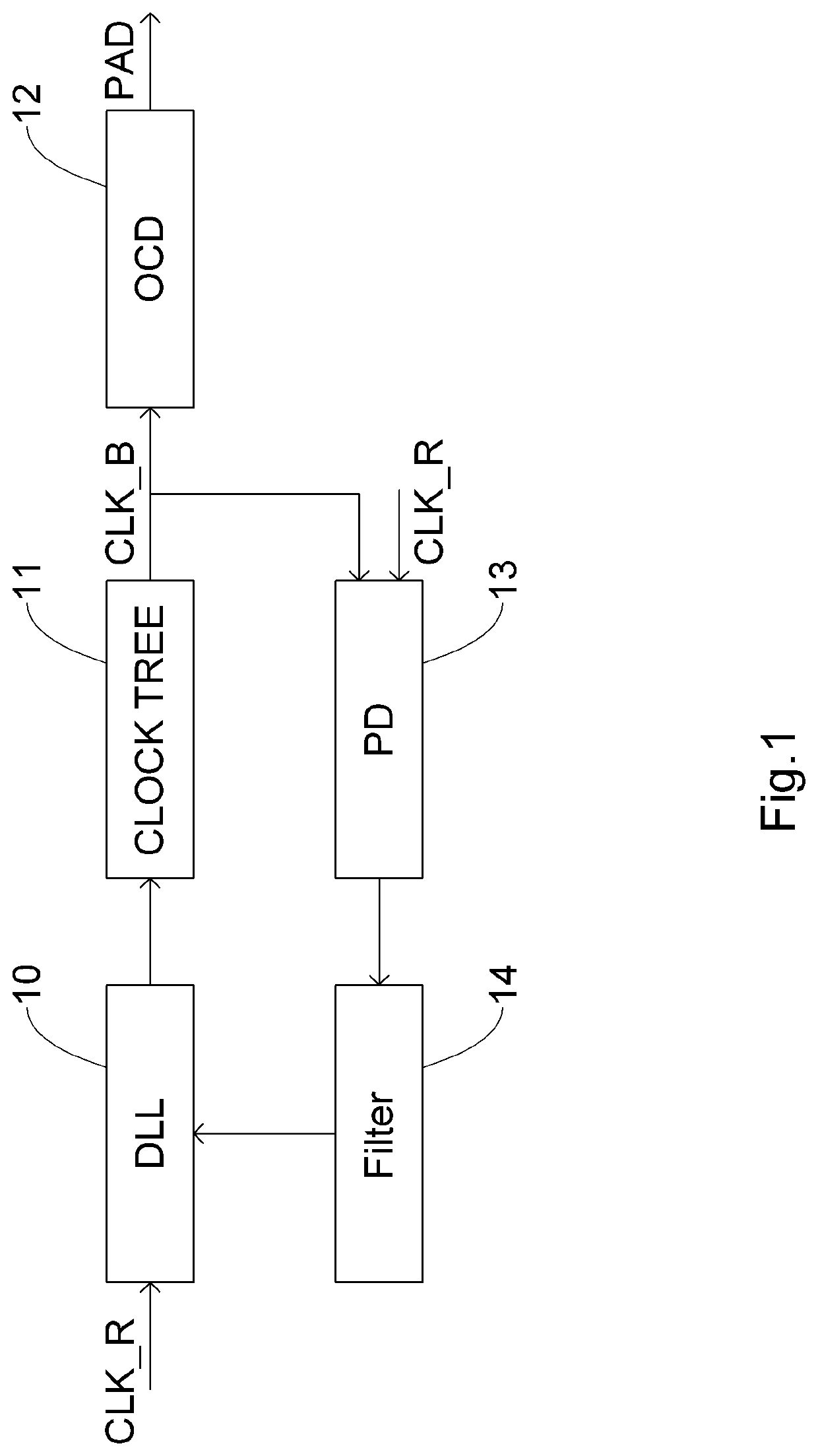
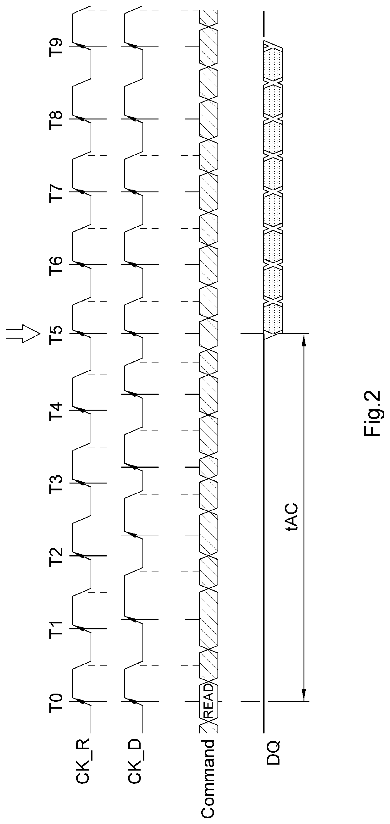
[0018]The present invention provides a control circuit and a method in order to increase the number of activations for the DLL to update the delay line after a READ command is received and before the DQ is prepared.

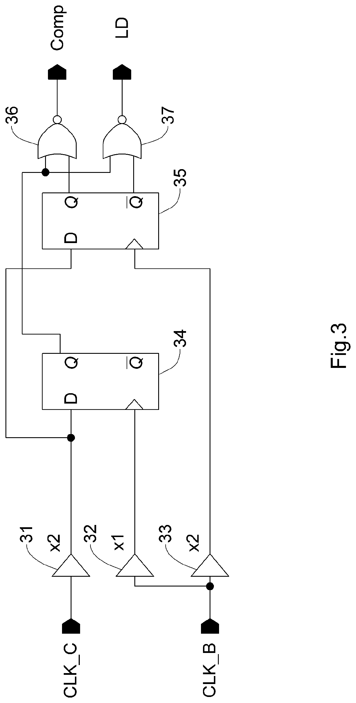
[0019]FIG. 3 illustrates a PD in accordance with an exemplary embodiment of the present invention. FIG. 4 illustrates a waveform and an output table that are useful for understanding the operation of the PD in FIG. 3. The PD is able to detect the relationship between an edge of the CLK_B and an edge of the CLK_R, and then obtain the information that an edge of the CLK_B is ahead of, behind or synchronized with the CLK_R. Next, in the present invention, based on the information, the filter activates the DLL to update the delay line according to the relationship between an edge of the CLK_B and an edge of the CLK_R. Further...


PUM


Abstract

A dynamic random access memory (DRAM) includes a delay lock loop (DLL), a clock tree, an off-chip driver (OCD), a phase detector (PD) and a filter. The DLL receives a reference clock and updates a delay line, and then outputs a calibrated clock via the clock tree; the PD receives the calibrated clock via the clock tree and detects a phase difference between the calibrated clock and the reference clock; and the filter activates the DLL to update the delay line according the phase difference, wherein when a READ command is received, the filter increases the number of activations for the DLL to update the delay line, thereby shortening the access time of the DRAM.

Description

BACKGROUND1. Technical Field[0001]This present invention relates to a delay lock loop (DLL) in a dynamic random access memory (DRAM), and in particular relates to the controlling of the DLL in the dynamic random access memory when data is being accessed.2. Description of Related Art[0002]As CPU speeds continue to increase, memory performance becomes more of a limiting factor in system performance. An important aspect of increasing memory performance is increasing the speed at which data can be transmitted to and from DRAMs. In high-speed DRAM technologies such as RDRAM and DDR, a DLL is a circuit designed to minimize the phase difference between the reference clock (input clock) and the control signals.[0003]FIG. 1 illustrates a prior art control circuit for controlling a DLL 10 in a DRAM. The DRAM includes the DLL 10, a clock tree 11, at least one off-chip driver (OCD) 12, a phase detector (PD) 13 and a filter 14. The DLL 10 receives a reference clock (CLK_R) and updates a delay li...

Claims


Application Information

Patent Timeline
Patent Type & Authority Patents(United States)
IPC IPC(8): G11C7/10H03L7/093H03L7/095G11C7/22G11C11/4076H03L7/081G11C11/409H03L7/085
CPCG11C7/222H03L7/085H03L7/095G11C11/4076H03L7/0818G11C11/409G11C7/1066H03L7/093
Inventor CHANG, CHUAN-JENLEE, WEN-MING
Owner NAN YA TECH
Why Eureka
Try Eureka