
Automobile member

a technology for automobiles and components, applied in the field of automobile members, can solve the problems of limited deformation caused by elastic deformation of floor panels, difficult for the impact absorption structure in the front portion of the vehicle to sufficiently absorb impact energy, and distortion of side sills, etc., to limit spot fractures, reduce impact energy absorption amount, and reduce manufacturing yield

Active Publication Date: 2020-03-03
NIPPON STEEL CORP
View PDF25 Cites 0 Cited by
  • Summary
  • Abstract
  • Description
  • Claims
  • Application Information

AI Technical Summary

Benefits of technology

This configuration enables the production of automobile members with improved manufacturing yield and increased impact energy absorption capabilities, effectively addressing the issues of spot fractures and enhancing collision safety performance.

Problems solved by technology

While a vehicle is traveling, deflection caused by elastic deformation of the floor panel is limited by the side sill.
Moreover, at the time of a collision of the vehicle, the side sill also plays a role of being distorted due to an input impact load and absorbing impact energy.
In such a small overlap head-on collision, since the outer side of an impact absorption structure (for example, a frontside member) provided in a front portion of the vehicle collides with the fixed barrier, it is difficult for the impact absorption structure in the front portion of the vehicle to sufficiently absorb impact energy.
However, as a result of the small overlap head-on collision test, it has been ascertained that axial collapse distortion occurs in a side sill at the time of a collision so that impact energy is absorbed by the side sill.
In addition, at the time of a head-on collision of a vehicle, the frontside member also plays a role of causing bending distortion due to an impact load input via a front crash box disposed in the front end portion and absorbing collision energy.

Method used


Image

  • Automobile member
  • Automobile member
  • Automobile member

Examples


examples

[0225]Hereinafter, an effect of the aspect of the present invention will be described in more detail with reference to Examples. However, the conditions for Examples are examples of conditions employed to check the feasibility and the effect of the present invention, and the present invention is not limited to the examples of the conditions. The present invention can employ various conditions as long as the object of the present invention is achieved without departing from the gist of the present invention.

[0226][Inspection of Impact Absorption Performance of Side Sill]

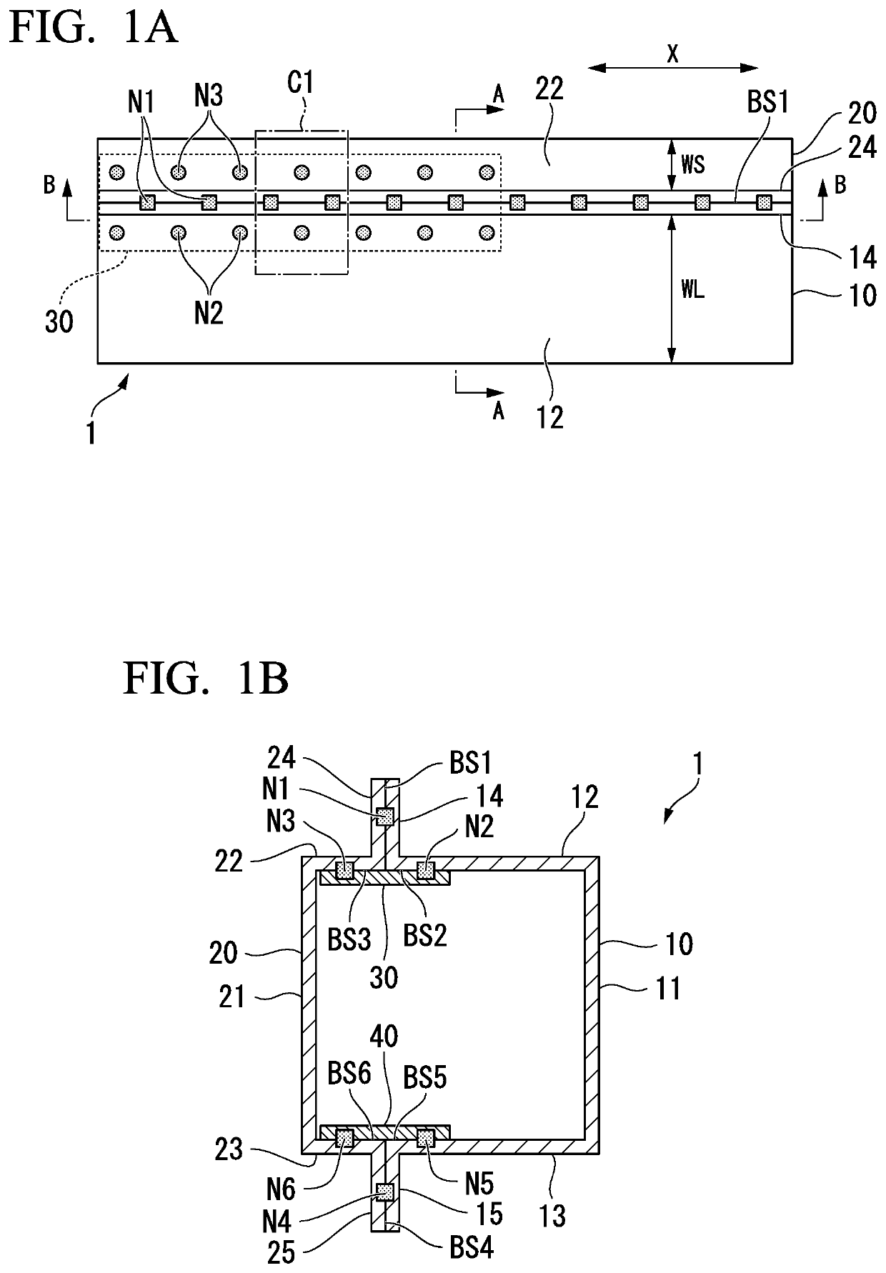
[0227]In order to inspect the impact absorption performance of side sills, five kinds of side sills E1 to E5 shown in FIGS. 15(a) to 15(e) were prepared. In FIG. 15, for convenience of description, the reference sign used in the descriptions of the first and second embodiments was applied to each of the constituent elements of the side sills E1 to E5.

[0228]The side sill E1 shown in FIG. 15(a) was a side sill prepared ...


PUM


Abstract

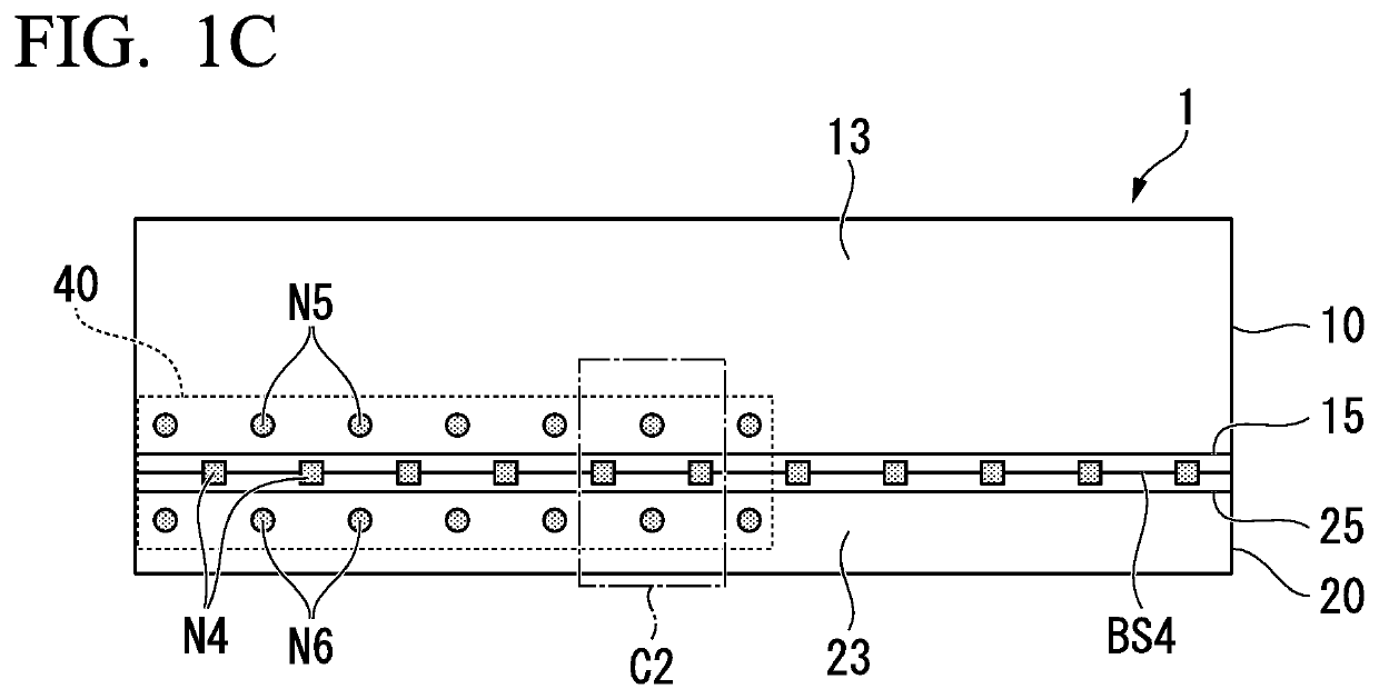
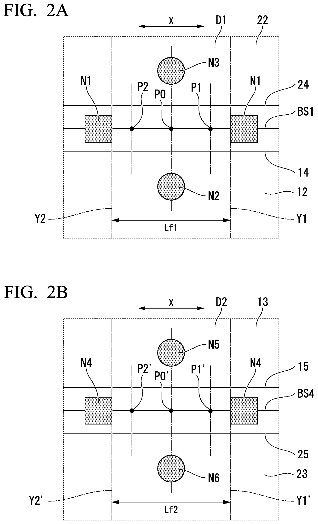
Provided is an automobile member including a hat-shaped first member that has a first flange, a second flange, a first wall portion erected from the first flange, a second wall portion erected from the second flange, and a web connecting the first and second wall portions to each other; a second member that is spot-joined to the first and second flanges; a first joining plate that is joined to inner wall surfaces of the first wall portion and the second member; and a second joining plate that is joined to inner wall surfaces of the second wall portion and the second member.

Description

TECHNICAL FIELD OF THE INVENTION[0001]The present invention relates to an automobile member.[0002]Priority is claimed on Japanese Patent Application No. 2016-030224, filed on Feb. 19, 2016, the content of which is incorporated herein by reference.RELATED ART[0003]Most of body shells of vehicle bodies of automobiles having a so-called monocoque structure include a platform, left and right body sides, and an engine compartment provided in a front part of the body shell. The platform has a floor panel. The left and right body sides are mounted on both sides of the platform. The engine compartment has a frontside member as its constituent member.[0004]The body side has an A pillar, a B pillar, a roof rail side, and a side sill (kicker). The roof rail side is welded to an upper end portion of each of the A pillar and the B pillar. As welding for automobile members, resistance spot welding (which will hereinafter be abbreviated to spot welding), laser welding, and the like are mainly used...

Claims


Application Information

Patent Timeline
Patent Type & Authority Patents(United States)
IPC IPC(8): B62D27/02B62D21/15B62D25/02B62D29/00B62D25/20
CPCB62D21/152B62D27/023B62D21/157B62D29/005B62D25/025B62D25/2027B62D21/00B62D25/00B62D25/04B62D25/20
Inventor OTSUKA, KENICHIRO
Owner NIPPON STEEL CORP
Learn More