Secondary battery separator comprising organic/inorganic composite porous layer, and manufacturing method therefor

a composite porous layer and secondary battery technology, applied in the field of porous separators, can solve the problems of high thermal shrinkage of the separator made of polyolefin, battery performance degradation, and high risk of failure, and achieve superior heat resistance and mechanical properties, outstanding air permeability characteristics, and less prone

Active Publication Date: 2020-01-21
LG ENERGY SOLUTION LTD
View PDF27 Cites 0 Cited by
  • Summary
  • Abstract
  • Description
  • Claims
  • Application Information

AI Technical Summary

Benefits of technology

[0027]The separator for a secondary battery manufactured by the claimed method for manufacturing a separator has superior heat resistance and mechanical properties because the separator is less prone to the occurrence of surface defects during drying. Furthermore, the binder polymer particles in the organic / inorganic composite porous layer do not penetrate into the pores of the separator substrate, resulting in outstanding air permeability characteristics.

Problems solved by technology

However, a separator made of polymer including polyolefin has high thermal shrinkage at high temperature and a risk of failure caused by dendrite growth.
In this case, however, because the binder solution is apt to penetrate into the pores of the porous substrate, a large amount of binders need to be used to show sufficient adhesion between the inorganic material and the porous substrate surface, resulting in battery performance degradation. FIG. 2 shows a separator having a composite porous layer according to prior art, and as in the illustrated example, the binder resin dissolved in the organic solvent penetrates into the pores of the porous substrate and blocks the pores of the porous substrate.
Moreover, as the binder concentration in the slurry increases, the slurry viscosity greatly increases, making it difficult to form a thin-film organic / inorganic composite layer and high temperature is required in the drying process, and when the slurry viscosity is maintained at low level, adhesion with the porous substrate or adhesion between the inorganic material is lowered, causing the inorganic particles to easily detach.
As the organic solvent-based process involves a long dry zone of a dry line during drying due to the critical explosion limit, the slurry changes in concentration and rheological properties by solvent evaporation in the slurry preparation and transfer and coating processes, which may affect the coating quality of final products.
This method also uses ionic polymer that is soluble in water, but not disperse and completely dissolves it in water, inevitably encountering a phenomenon in which the solvent is trapped, and a larger amount of organic solvent such as diethylacetamide solvent is used 15 times than water, failing to provide a technical motivation to a coating method using an aqueous solvent, and besides, it is necessary to add crosslinker and initiator together to an organic solvent in the slurry preparation process to induce chemical crosslinking after coating for the benefit of increased adhesion with the substrate, and heat or UV treatment for 20 hours or longer is absolutely required in the drying process.
However, when crosslinker and initiator are added to the slurry solution, partial self-crosslinking takes place by heat and energy applied from the outside environment in the process of storage and transfer of the coating solution before applied to the porous substrate, promoting solidification of the slurry, eventually resulting in reduced uniformity of the coated separator.
Furthermore, because long-time heat treatment and UV treatment is necessary during drying, the output of the manufacturing process is limited, and the thin-film porous substrate may be damaged by high temperature / high energy during drying, causing property degradation and air permeability reduction.

Method used


Image

  • Secondary battery separator comprising organic/inorganic composite porous layer, and manufacturing method therefor
  • Secondary battery separator comprising organic/inorganic composite porous layer, and manufacturing method therefor
  • Secondary battery separator comprising organic/inorganic composite porous layer, and manufacturing method therefor

Examples


example 1

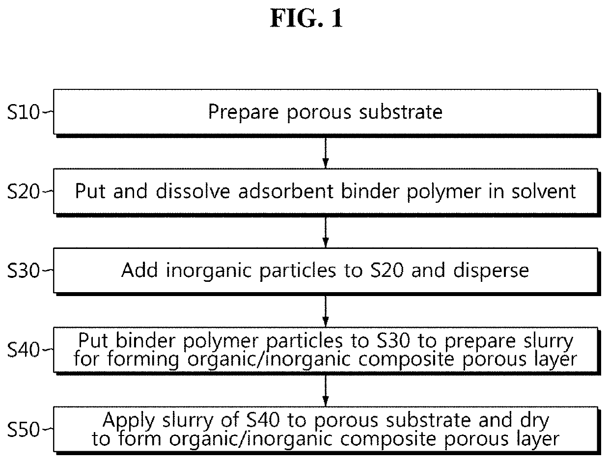
[0081]Al2O3 (Nippon light metal, LS235, particle size 510 nm), waterborne acrylic emulsion (Toyo ink, CSB130, solids 40%, particle size 177 nm), and carboxymethylcellulose (GL Chem, SG-L02, radius of gyration 25 nm) were put in water at a ratio of 98:1:1 and stirred to obtain a uniform dispersion slurry. The slurry was applied to one surface of a polyethylene porous substrate (W scope, WL11B, air transmission time 150 sec / 100 cc) using a doctor blade and dried with cool air to manufacture a porous separator having an organic / inorganic composite porous layer. The air transmission time of the manufactured separator was at the level of 153 sec / 100 cc that was almost unchanged when compared to the air transmission time of the polymer substrate before formation of the organic / inorganic composite porous layer.

example 2

[0082]Except that Al2O3 was replaced with AlOOH (Nabaltec, Actilox200SM, particle size 230 nm), and a mix ratio of a slurry was adjusted such that a ratio of inorganic particles:organic particles:thickener was 94:3:3 on the basis of a weight ratio, a porous separator was manufactured in the same way as example 1. The air transmission time of the manufactured separator was at the level of 163 sec / 100 cc that was almost unchanged when compared to the air transmission time of the polymer substrate before formation of the organic / inorganic composite porous layer.


PUM

PropertyMeasurementUnit
particle sizeaaaaaaaaaa
radius of gyrationaaaaaaaaaa

Abstract

The present invention relates to a secondary battery separator, and a manufacturing method therefor. The secondary battery separator according to the present invention comprises an organic / inorganic composite porous layer for improving thermal resistance and physical strength, and since the organic / inorganic composite porous layer uses polymer particles as a binder, the secondary battery separator, compared with a separator using a solvent-type binder resin using organic solvents, exhibits excellent permeability.

Description

CROSS-REFERENCE TO RELATED APPLICATIONS[0001]The present application is a national phase entry under 35 U.S.C. § 371 of International Application No. PCT / KR2015 / 011330, filed Oct. 26, 2015, published in Korean, which claims priority from Korean Patent Application No. 10-2014-0145532 filed Oct. 24, 2014, the disclosures of which are hereby incorporated herein by reference.TECHNICAL FIELD[0002]The present disclosure relates to a separator used in an electrochemical device such as a secondary battery and a method for manufacturing the same. More particularly, the present disclosure relates to a porous separator having an organic / inorganic composite porous layer with improved air permeability characteristics and a method for manufacturing the same.BACKGROUND ART[0003]A secondary battery is an energy storage that is basically made up of positive electrode / negative electrode / separator / electrolyte solution and can be recharged by reversible conversion between chemical energy and electrical...

Claims


Application Information

Patent Timeline
Patent Type & Authority Patents(United States)
IPC IPC(8): H01M2/16H01M2/18H01M10/0525C08F2/22C08F10/00H01M50/403H01M50/449H01M50/463
CPCH01M10/0525H01M2/1633H01M2/18C08F2/22C08F10/00H01M50/403H01M50/446H01M50/449H01M50/463Y02E60/10
Inventor LEE, JOO-SUNGKIM, JI-EUNYU, IN-GYOUNGJIN, SUN-MIHAN, DA-KYUNG
Owner LG ENERGY SOLUTION LTD
Why Eureka
Try Eureka