
Fiber-optic current sensor with spun fiber and temperature compensation

a technology of current sensor and fiber, applied in the field of fiber-optic current sensor, can solve the problems of limiting the possible number of fiber loops, inability to detect the minimum detectable current at a given detection bandwidth (measuring time), and inability to stabilize and temperature-dependent signals, etc., and achieve good temperature compensation

Inactive Publication Date: 2019-07-09
HITACHI ENERGY SWITZERLAND AG
View PDF17 Cites 0 Cited by
  • Summary
  • Abstract
  • Description
  • Claims
  • Application Information

AI Technical Summary

Benefits of technology

The present invention is about a fiber-optic current sensor that can detect electric current using a special type of fiber that has strong birefringence and good temperature compensation. This improves the accuracy and reliability of the sensor's measurement.

Problems solved by technology

Mechanical stress in the fiber, which may be present due to bending of the fiber to a coil, fiber packaging, or hardening of the coating at low temperatures, has a significant influence on the evolution of light polarization in the fiber and may result in an unstable and temperature-dependent signal.
Bend-induced stress can limit the possible number of fiber loops, particularly at small loop diameters, to a few loops.
As a result the minimum detectable current at a given detection bandwidth (measuring time) is then limited correspondingly.
Thermal annealing of the fiber coils has been used to remove bend-induced stress, but tends to be a sophisticated and time-consuming procedure [2, 3].
Again the removal of the coating and the insertion of the fiber into a capillary is a time consuming effort.

Method used


Image

  • Fiber-optic current sensor with spun fiber and temperature compensation
  • Fiber-optic current sensor with spun fiber and temperature compensation
  • Fiber-optic current sensor with spun fiber and temperature compensation

Examples


Embodiment Construction

Definitions

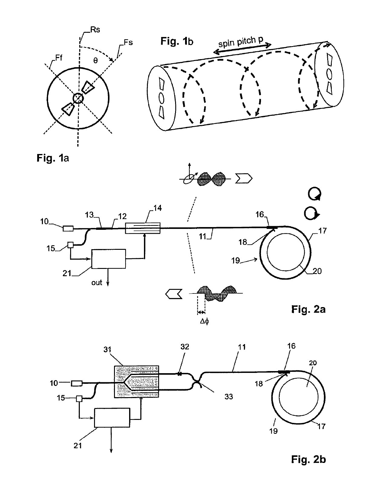
[0048]In the context of the present disclosure a highly-birefringent spun fiber is defined as a fiber with embedded linear birefringence, characterized in the wavelength range of interest by an average linear beat length LLB≤200 mm, and that has been spun during the manufacturing process with a spin pitch p≤100 mm. The process freezes the twist permanently into the fiber. As a result the fiber becomes circularly birefringent.

[0049]An alternative method to generate circular birefringence is twisting a single-mode fiber along its longitudinal axis after manufacturing and holding the fiber in that position against an elastic untwisting force. The invention disclosure addresses the first type of fiber but may be adapted to the latter type, as well.

[0050]A “Faraday rotator” in the sense used herein is an optical component containing a magneto-optic material and a permanent magnet that induces a Faraday rotation of the polarization of linearly polarized light by a given non-zer...


PUM


Abstract

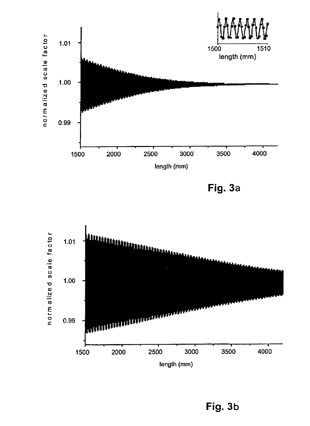
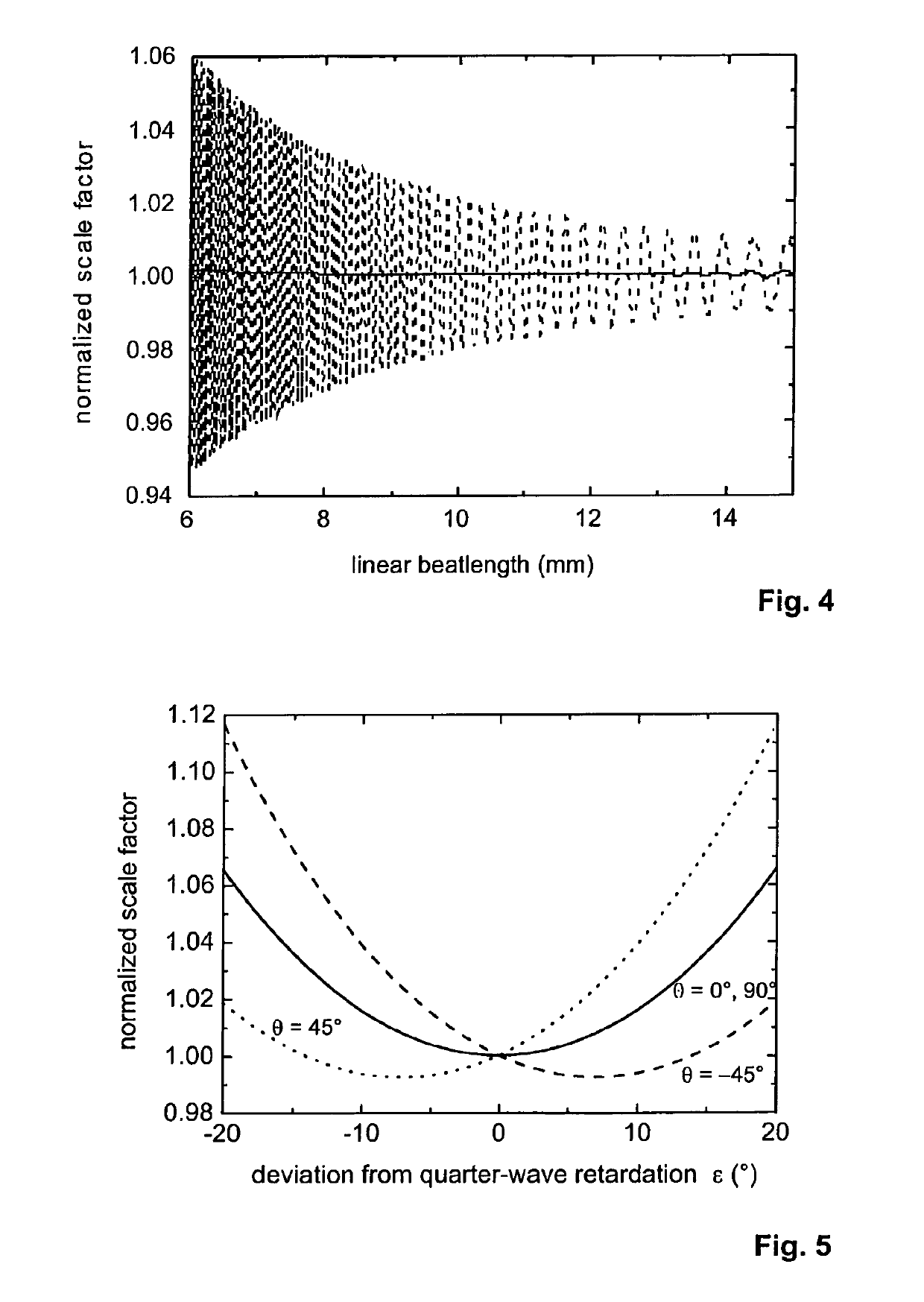
A fiber-optic current sensor uses a highly-birefringent spun fiber as sensing fiber. The light is fed through a retarder, which is a detuned quarter-wave or half-wave retarder. It is shown that such detuning can be used to compensate for temperature dependencies of the sensing head.

Description

FIELD OF THE INVENTION[0001]The invention relates to a fiber-optic current sensor with a strongly birefringent spun fiber.BACKGROUND OF THE INVENTION[0002]Fiber-optic current sensors commonly rely on the Faraday effect in a fused silica fiber. The sensing fiber forms a coil around a conductor that carries the current to be measured. The Faraday effect is observed either as a rotation of the polarization of linearly polarized light or equivalently as a differential phase shift between left and right circularly polarized light waves. In the latter case, the circular light states are commonly produced at the entrance to the sensing fiber by a short section of polarization-maintaining fiber acting as a quarter-wave retarder (QWR). Such a sensor is then designed in a reflective configuration with a mirror at the opposite end of the sensing fiber [1, 2]. Alternatively the sensor may be designed as a Sagnac-type interferometer [2] with QWRs (quarter-wave retarders) at both sensing fiber en...

Claims


Application Information

Patent Timeline
Patent Type & Authority Patents(United States)
IPC IPC(8): G01R15/24G01R33/032
CPCG01R15/246G01R33/0322
Inventor MUELLER, GEORGGU, XUNBOHNERT, KLAUSFRANK, ANDREAS
Owner HITACHI ENERGY SWITZERLAND AG
Learn More