Thermal flow sensor

A thermal flow sensor technology, applied in the direction of mass flow measurement devices, etc., can solve the problems of low precision and poor signal output stability, and achieve the effects of improving work efficiency, low price, and ensuring measurement accuracy and measurement stability

Inactive Publication Date: 2011-03-30
SHANGHAI JIECHENG MACHINERY & MOTOR +1
View PDF2 Cites 8 Cited by
  • Summary
  • Abstract
  • Description
  • Claims
  • Application Information

AI Technical Summary

Problems solved by technology

[0008] The purpose of the present invention is to provide a thermal flow sensor to solve the shortcomings of the existing thermal flow sensor, such as low precision and poor stability of signal output

Method used


Image

  • Thermal flow sensor
  • Thermal flow sensor
  • Thermal flow sensor

Examples


Embodiment Construction

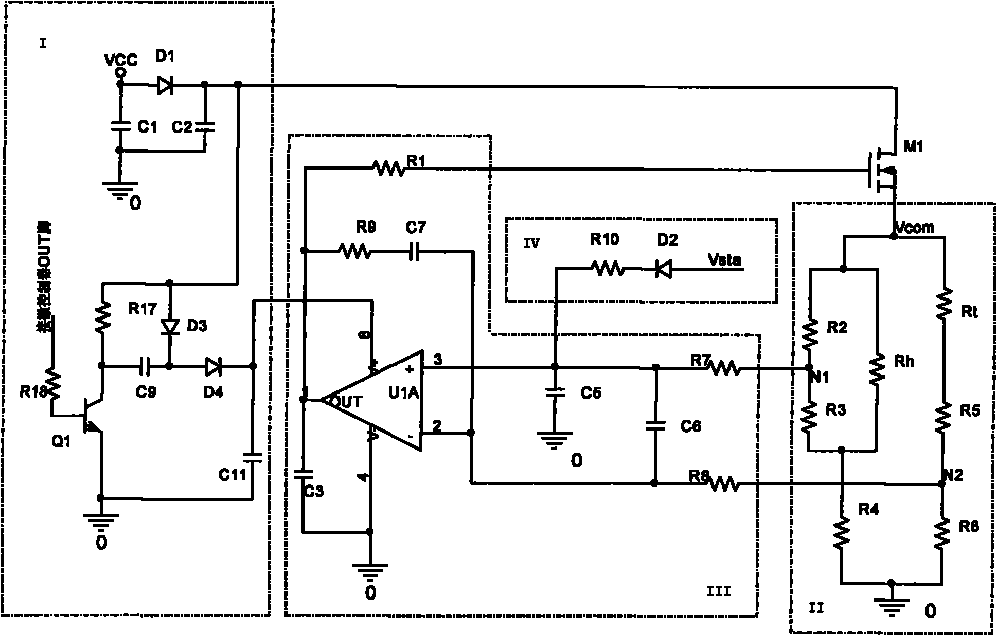
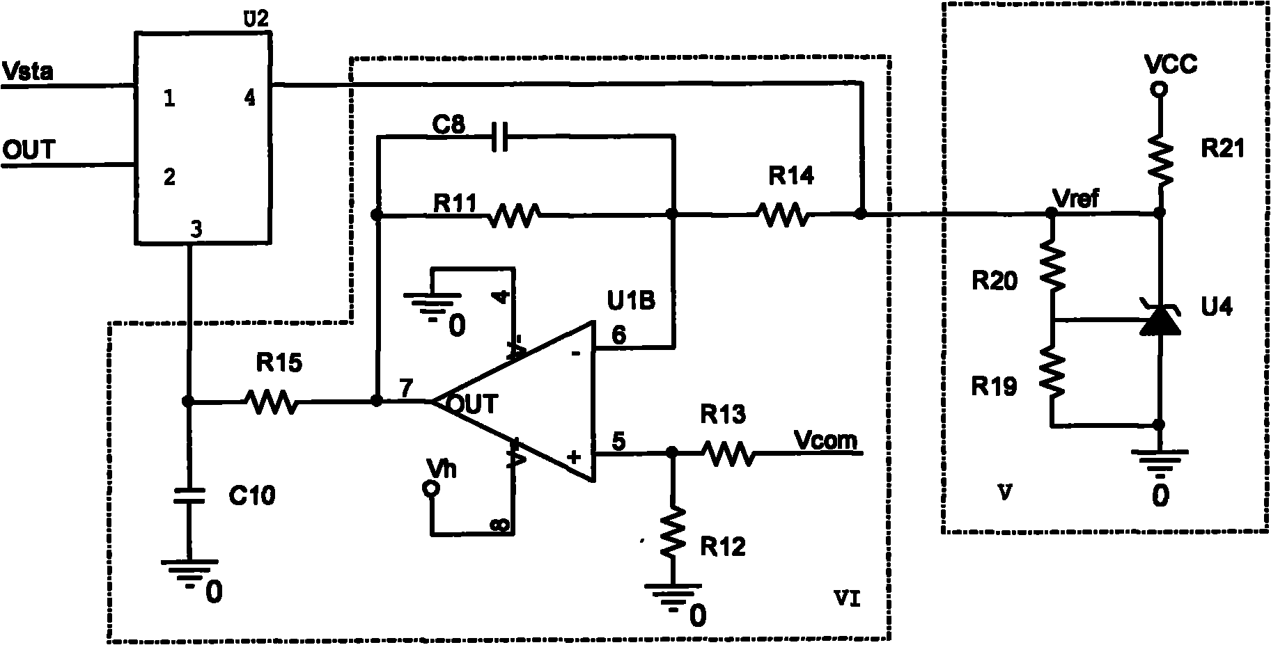
[0027] The present invention will be described in detail below in conjunction with the accompanying drawings. In order to facilitate the understanding of the present invention, the thermal flow sensor of the present invention is now divided into a pre-stage part and a post-stage part according to the functional distinction of each circuit. The pre-stage part is used to sense the current air mass flow rate and provide original information for the post-stage part. The post-stage part is used to complete the processing of the output signal of the pre-stage part, and complete the conditioning, filtering, conversion and output of the signal. The connection mentioned in the present invention specifically refers to a direct or indirect electrical connection between circuits or between circuits and components or components.

[0028] Firstly, the pre-stage part of the thermal flow sensor of the present invention will be described. It reflects the flow rate through the degree of heat ...


PUM


Abstract

The invention provides a thermal flow sensor, comprising a power circuit, a field-effect tube, a Wheatstone bridge, an operational amplifier circuit and a microcontroller, wherein the drain of the field-effect tube is connected with the power circuit; the Wheatstone bridge comprises two bridge arms on which a heating resistor and a temperature sensitive resistor are respectively arranged, and the common point of the two bridge arms is connected with the source electrode of the field-effect tube and serves as a detecting voltage output point reflecting the current air mass flow; the operational amplifier circuit is respectively connected with the intermediate nodes of the two arms of the Wheatstone bridge, and the output end of the operational amplifier circuit is connected to the grid electrode of the field-effect tube to adjust the current flowing through the heating resistor by controlling the current flowing out from the source electrode of the field-effect tube and ensure that the surface temperature of the heating resistor remains stable; and the input end of the microcontroller is connected with the source electrode of the field-effect tube and used for processing the detecting voltage of the source electrode of the field-effect tube and outputting a frequency signal showing the current air mass flow. The thermal flow sensor has the advantages of high precision, and strong stability.

Description

technical field [0001] The invention relates to a thermal flow sensor, in particular to a thermal flow sensor for automobiles. Background technique [0002] The thermal flow sensor is a sensor that uses the heat exchange relationship between the heat-generating substance in the airflow and the measured air to measure the current air mass flow rate. The air mass flow rate refers to the air mass flowing through it per unit time. Among them, the thermal flow sensor uses a heating resistor made of wire winding as a heating substance. The heating resistor is placed in the air flow, and its surface exchanges heat with the air. Some parameters of the heat exchange are detected by the sensor circuit, and the gas flow near the heating resistor is obtained, so as to calculate the gas flow of the entire pipeline. [0003] In addition, while the heating resistor is exchanging heat with the air, it is also necessary to keep the temperature of the heating resistor stable. Therefore, in a...

Claims


Application Information

Patent Timeline
Patent Type & Authority Applications(China)
IPC IPC(8): G01F1/76
Inventor 周爱国
Owner SHANGHAI JIECHENG MACHINERY & MOTOR
Why Eureka
Try Eureka