Abnormality diagnosis device and abnormality diagnosis method for internal combustion engine

a technology of abnormal diagnosis and internal combustion engine, which is applied in the direction of combustion engines, machines/engines, electric control, etc., can solve the problems of abnormality in the internal combustion engine and so as to suppress and the decline in the accuracy of abnormal diagnosis for the internal combustion engin

Inactive Publication Date: 2019-07-02
TOYOTA JIDOSHA KK
View PDF3 Cites 0 Cited by
  • Summary
  • Abstract
  • Description
  • Claims
  • Application Information

AI Technical Summary

Benefits of technology

[0010]According to the first and second aspects of the disclosure, an abnormality diagnosis device and an abnormality diagnosis method for an internal combustion engine in which a decline in the accuracy of an abnormality determination for the internal combustion engine is further suppressed can be provided.

Problems solved by technology

Accordingly, once whether or not the internal combustion engine is abnormal is determined based on the variation degree of the air-fuel ratios during the execution of the temperature rise processing, an erroneous determination that the internal combustion engine is abnormal may be made based on a large variation degree of the air-fuel ratios during the execution of the temperature rise processing regardless of the internal combustion engine being normal.
The erroneous determination may result in a decline in the accuracy of the abnormality determination.

Method used


Image

  • Abnormality diagnosis device and abnormality diagnosis method for internal combustion engine
  • Abnormality diagnosis device and abnormality diagnosis method for internal combustion engine
  • Abnormality diagnosis device and abnormality diagnosis method for internal combustion engine

Examples


Embodiment Construction

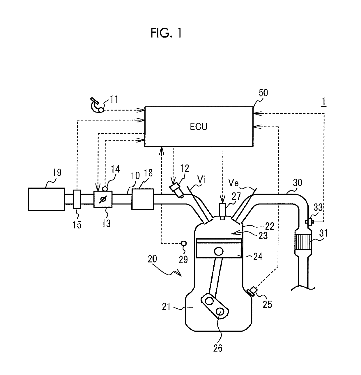
[0018]FIG. 1 is a schematic configuration diagram of an engine system 1. In an engine 20, a piston 24 reciprocates as an air-fuel mixture is combusted in a combustion chamber 23 inside a cylinder head 22 installed in the upper portion of a cylinder block 21 storing the piston 24. The reciprocation of the piston 24 is converted into the rotational motion of a crankshaft 26. The engine 20 is an in-line four-cylinder engine. However, the engine 20 is not limited thereto insofar as it has a plurality of cylinders.

[0019]An intake valve Vi opening and closing an intake port and an exhaust valve Ve opening and closing an exhaust port are disposed for each cylinder in the cylinder head 22 of the engine 20. An ignition plug 27 for igniting the air-fuel mixture in the combustion chamber 23 is attached for each cylinder to the top portion of the cylinder head 22.

[0020]The intake port of each cylinder is connected to a surge tank 18 via a branch pipe for each cylinder. An intake pipe 10 is conn...


PUM


Abstract

An abnormality diagnosis device for an engine includes an electronic control unit configured to execute temperature rise processing by controlling an air-fuel ratio of at least one of a plurality of cylinders to be a rich air-fuel ratio and controlling an air-fuel ratio of each of the other cylinders to be a lean air-fuel ratio. The electronic control unit is configured to determine whether or not the execution of the temperature rise processing is ongoing, to execute abnormality determination processing to determine whether or not the engine is in an abnormal state, to execute the abnormality determination processing based on whether or not the variation degree during stop of the temperature rise processing exceeds a first determination value, and to execute the abnormality determination processing based on whether or not the variation degree during the execution of the temperature rise processing exceeds a second determination value.

Description

INCORPORATION BY REFERENCE[0001]The disclosure of Japanese Patent Application No. 2017-032630 filed on Feb. 23, 2017 including the specification, drawings and abstract is incorporated herein by reference in its entirety.BACKGROUND1. Technical Field[0002]The disclosure relates to an abnormality diagnosis device and an abnormality diagnosis method for an internal combustion engine.2. Description of Related Art[0003]Controlling the air-fuel ratio of at least one of a plurality of cylinders of an internal combustion engine to be a rich air-fuel ratio and controlling the air-fuel ratio of each of the other cylinders to be a lean air-fuel ratio is known as temperature rise processing in which the temperature of a catalyst controlling the exhaust gas of the internal combustion engine is raised (refer to, for example, Japanese Unexamined Patent Application Publication No. 2012-057492 (JP 2012-057492 A)).SUMMARY[0004]An abnormality diagnosis device is known with regard to the internal combus...

Claims


Application Information

Patent Timeline
Patent Type & Authority Patents(United States)
IPC IPC(8): F02D41/22F02D41/02F02D41/00F02D41/30F02D41/14
CPCF02D41/22F02D41/008F02D41/025Y02T10/26F02D41/1495F02D41/3094F02D41/1454F02D41/024F02D41/068Y02T10/12
Inventor NAKAMURA, TAKASHINOSE, YUKIIKUTA, EIJI
Owner TOYOTA JIDOSHA KK
Why Eureka
Try Eureka