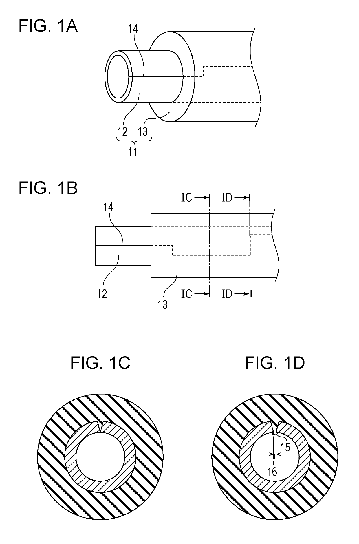
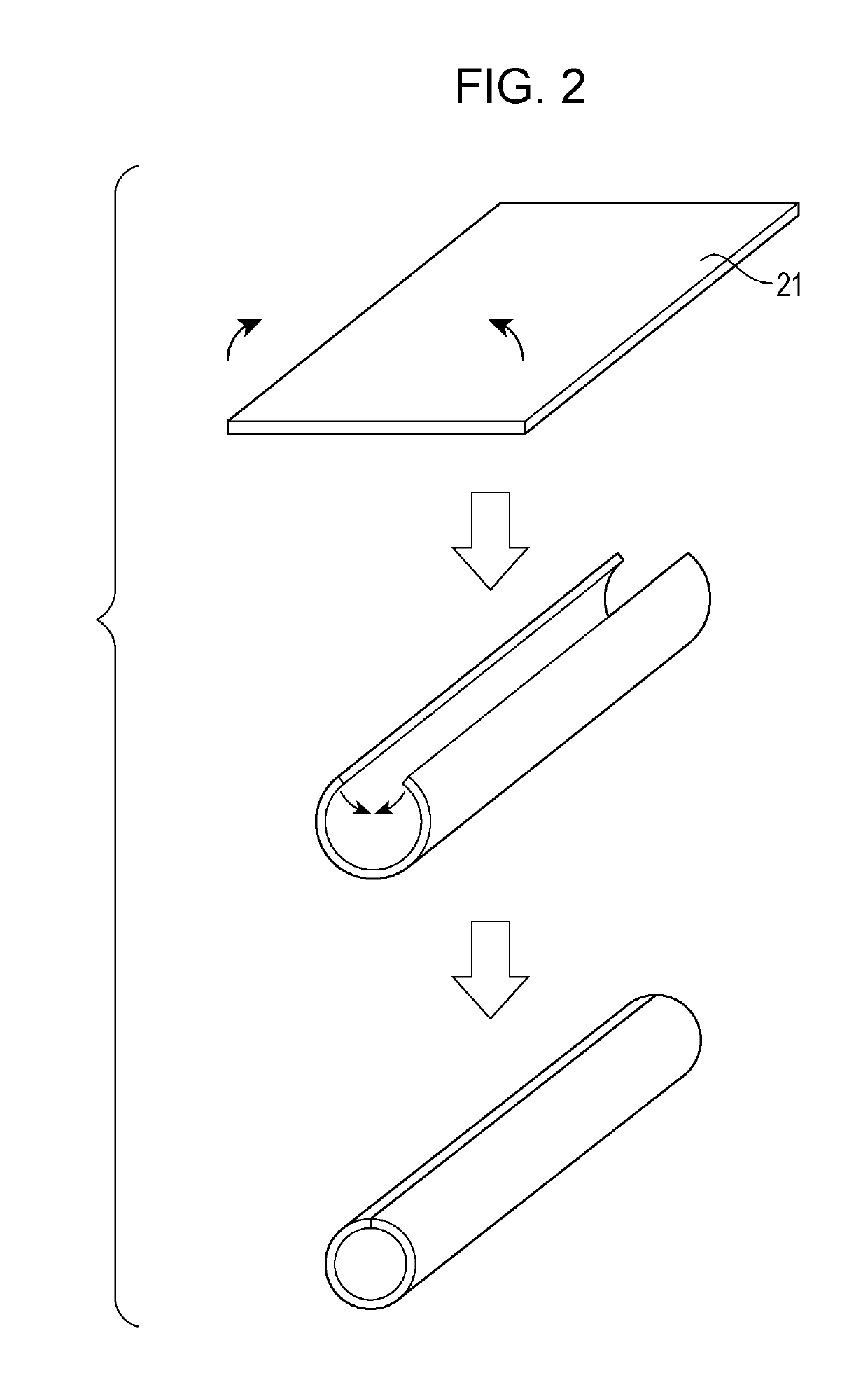
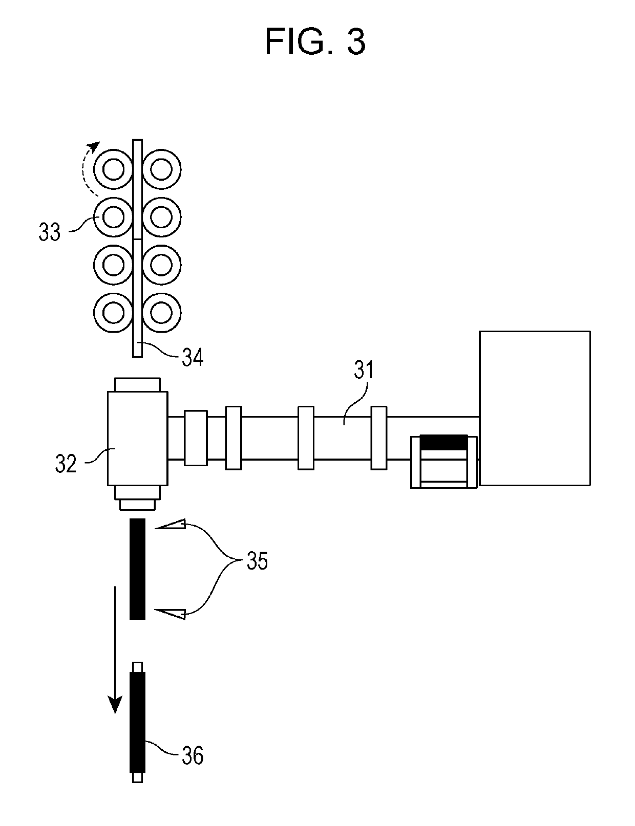
Electrophotographic roller, production method therefor, and electrophotographic apparatus
a technology of electrophotography and roller, which is applied in the direction of instruments, applications, corona discharge, etc., can solve the problems of rare uniformity of conveying speed of recording materials, and achieve the effect of reducing the separation between a base and a conductive elastic layer and avoiding the deformation of the film
- Summary
- Abstract
- Description
- Claims
- Application Information
AI Technical Summary
Benefits of technology
Problems solved by technology
Method used
Image
Examples
embodiments
[0068]While the present disclosure will be specifically described below by using embodiments and comparative embodiments, the disclosure is not limited to these embodiments. Prior to descriptions of the embodiments, descriptions will be given of preparation examples of coating liquid for a front surface and evaluation methods for an electrophotographic roller.
First Production Example: Preparation of Coating Liquid 1
[0069]Urethane resin was obtained by reacting polycaprolactone-based polyol and tolylene diisocyanate (TDI) and was dissolved in a methyl isobutyl ketone to form a solution so that the resin component became about 27 mass %. Further, 30 mass % of carbon black as a conductive agent relative to the resin component and 50 mass % of acrylic particles relative to the resin component were added to the solution. The solution was sufficiently stirred and dispersed, and Coating Liquid 1 was thereby prepared.
Second Production Example: Preparation of Coating Liquid 2
[0070]Urethane r...
third embodiment
[0101]As a base, a cylindrical base made of stainless steel and having a comb tooth shape similar to that of the first embodiment was used. The sizes of portions of the comb tooth shape are shown in Table 3. A surface layer having a thickness of 15 μm was formed by applying coating liquid 1 onto a surface of an elastic layer after formation of the elastic layer, and the material was set by air drying for 30 minutes at room temperature and further drying using a hot-air circulating drier for 1 hour at a temperature of 160° C. As a result, an electrophotographic roller No. 3 was obtained similarly to the first embodiment except for the above steps. Further, Image Evaluation 1 and misalignment evaluation were performed similarly to the first embodiment. The evaluation results are shown in Table 3. FIG. 7A is a schematic cross-sectional view of the electrophotographic roller No. 3. Reference numeral 71 denotes a surface layer.
fourth embodiment
[0102]Materials in column Component (1) of the following Table 2 were mixed for 7 minutes by using a 6-liter pressure kneader. Further, materials in column Component (2) of Table 2 were added, and the materials of columns (1) and (2) were kneaded for 15 minutes by an open roll, so that an unvulcanized rubber composition was produced.
[0103]
TABLE 2Parts byMaterialsmassCom-NBR (trade name: “Nipol DN401LL”, from 70ponentZeon Corporation)(1)Epichlorohydrin / ethylene oxide / allyl glycidyl 30ether terpolymer (trade name: “EPICHLOMER CG102”, from Daiso Co., Ltd.)Carbon black (trade name: “Asahi #35G”, from 40ASAHI CARBON CO., LTD.)Zinc stearate (trade name: “ZINC STEARATE”, 3from NOF CORPORATION)Stearate (trade name: “Stearic acid Tsubaki”, 1from NOF CORPORATION)Com-OBSH with median diameter of 3.3μm (trade name:1.5ponent“NEOCELLBORN-N-1000M”, from EIWA (2)CHEMICAL IND. CO., LTD)OBSH with median diameter of 14.1 μm (trade 0.5name: “NEOCELLBORN-N-1000S”, from EIWA CHEMICAL IND. CO., LTD)Dibenz...
PUM
| Property | Measurement | Unit |
|---|---|---|
| thickness | aaaaa | aaaaa |
| width | aaaaa | aaaaa |
| temperature | aaaaa | aaaaa |
Abstract
Description
Claims
Application Information
 - R&D
- Intellectual Property
- Life Sciences
- Materials
- Tech Scout
- Unparalleled Data Quality
- Higher Quality Content
- 60% Fewer Hallucinations
Browse by: Latest US Patents, China's latest patents, Technical Efficacy Thesaurus, Application Domain, Technology Topic, Popular Technical Reports.
© 2025 PatSnap. All rights reserved.Legal|Privacy policy|Modern Slavery Act Transparency Statement|Sitemap|About US| Contact US: help@patsnap.com


