
Variable focal length lens system including a focus state reference subsystem

Active Publication Date: 2019-05-07
MITUTOYO CORP
View PDF10 Cites 8 Cited by
  • Summary
  • Abstract
  • Description
  • Claims
  • Application Information

AI Technical Summary

Benefits of technology

The patent describes a variable focal length (VFL) lens system that includes a VFL lens, a controller, a camera, an objective lens, an exposure time controller, and a focus state reference subsystem. The system uses a set of focus state reference regions, which are input through a reference object optics configuration and transmitted through the objective lens to the camera during image exposure. The focus state reference regions have known image locations in reference object images, which are used to determine the system focus reference state. The system can automatically adjust the optical power and effective focus position of the VFL lens to capture a best-focus image of a particular reference region. The VFL lens system can be used in a variety of applications, such as industrial inspection or microsurgery.

Problems solved by technology

While such VFL lenses can change effective focus position at a very high rate, variations in conditions such as temperature slightly alter their resonant characteristics and give rise to changes in optical power and modulation frequency, which may affect system performance and accuracy.

Method used


Image

  • Variable focal length lens system including a focus state reference subsystem
  • Variable focal length lens system including a focus state reference subsystem
  • Variable focal length lens system including a focus state reference subsystem

Examples


first embodiment

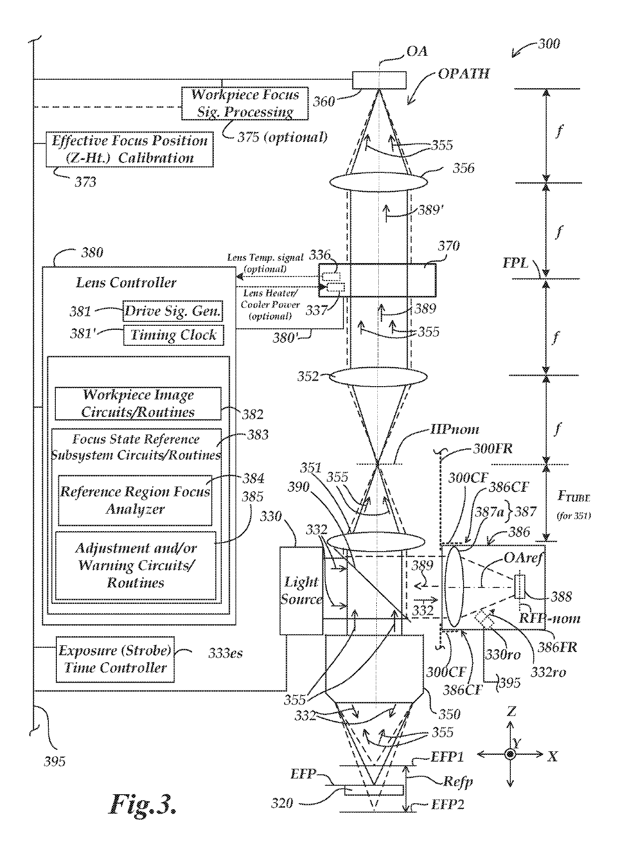
[0073]FIG. 4 includes two related diagrams. a reference object 488 is shown in a plan view in diagram 400A. The diagram 400B is a side view diagram, wherein the reference object 488 is shown tilted at a tilt angle TA, as imaged using the reference object optics configuration 487, in a first implementation of focus state reference subsystem 486 according to principles disclosed herein. The focus state reference subsystem 486 may be operated as, or substitute for, the focus state reference subsystem 386 described with reference to FIG. 3 and its operation may be understood, in part, based on previous description.

[0074]As shown in the diagram 400A, the reference object 488 has a planar “pattern surface” that includes a contrast pattern CP arranged along at least a portion of its periphery. It is generally desirable that the contrast pattern CP include high contrast edges arranged at a high spatial frequency and to allow the determination of a quantitative contrast or focus metric for r...

second embodiment

[0096]a reference object 888 is shown in a plan view in diagram 800A. The diagram 800B is a side view diagram, wherein the reference object 888 is shown as imaged using the reference object optics configuration 887, in a second implementation of focus state reference subsystem 886, according to principles disclosed herein. The focus state reference subsystem 886 may be operated as, or substitute for, the focus state reference subsystem 386 described with reference to FIG. 3 and its operation may be understood, in part, based on the previous description.

[0097]As shown in the diagrams 800A and 800B, the reference object 888 has three planar “pattern surfaces”, Layer0, Layer2, and Layer1 that include a contrast pattern CP arranged in various focus state reference regions (FSRR) at their periphery. Layer0, Layer2, and Layer1 are at different focus positions along the optical axis OAref within (and defining) the reference object focus range Rro. It will be understood that the FSRRs may o...


PUM


Abstract

A focus state reference subsystem comprising a focus state (FS) reference object is provided for use in a variable focal length (VFL) lens system comprising a VFL lens, a controller that modulates its optical power, and a camera located along an optical path including an objective lens and the VFL lens. Reference object image light from the FS reference object is transmitted along a portion of the optical path through the VFL lens to the camera. Respective FS reference regions (FSRRs) of the FS reference object include a contrast pattern fixed at respective focus positions. A camera image that includes a best-focus image of a particular FSRR defines a best-focus reference state associated with that FSRR, wherein that best-focus reference state comprises a VFL optical power and / or effective focus position of the VFL lens system through the objective lens.

Description

CROSS-REFERENCE TO RELATED APPLICATION(S)[0001]This application is a continuation-in-part of U.S. patent application Ser. No. 15 / 850,149, titled “VARIABLE FOCAL LENGTH LENS SYSTEM INCLUDING A FOCUS STATE REFERENCE SUBSYSTEM” filed on Dec. 21, 2017, the disclosure of which is hereby incorporated herein by reference in its entirety.BACKGROUNDTechnical Field[0002]This disclosure relates to precision metrology using a high speed variable focal length (VFL) lens (e.g., in a machine vision inspection system), and more particularly to monitoring the focus state of a VFL imaging system and / or optical power of a high speed variable focal length lens in that imaging system.Description of the Related Art[0003]Precision non-contact metrology systems such as precision machine vision inspection systems (or “vision systems” for short) may be utilized to obtain precise dimensional measurements of objects and to inspect various other object characteristics, and may include a computer, a camera and o...

Claims


Application Information

Patent Timeline
IPC IPC(8): G02B21/00H04N5/235G02B7/10G02B27/10G03B13/34
CPCG02B21/006G02B27/10G03B13/34G02B7/102H04N5/2353G02B21/361G02B3/14H04N23/67G02B21/00H04N23/73
Inventor NAHUM, MICHAELSUMMERS, JOSEPH ANDREWBRYLL, ROBERT KAMILGLADNICK, PAUL GERARD
Owner MITUTOYO CORP
Learn More