Wavelength tunable laser device and laser module
a laser device and laser module technology, applied in the direction of laser output parameters control, laser details, instruments, etc., can solve the problems of large variations in reflectance in the overlap portions, the fundamentally more difficult to achieve single-mode oscillation, and the mode spacing
- Summary
- Abstract
- Description
- Claims
- Application Information
AI Technical Summary
Benefits of technology
Problems solved by technology
Method used
Image
Examples
embodiment 1
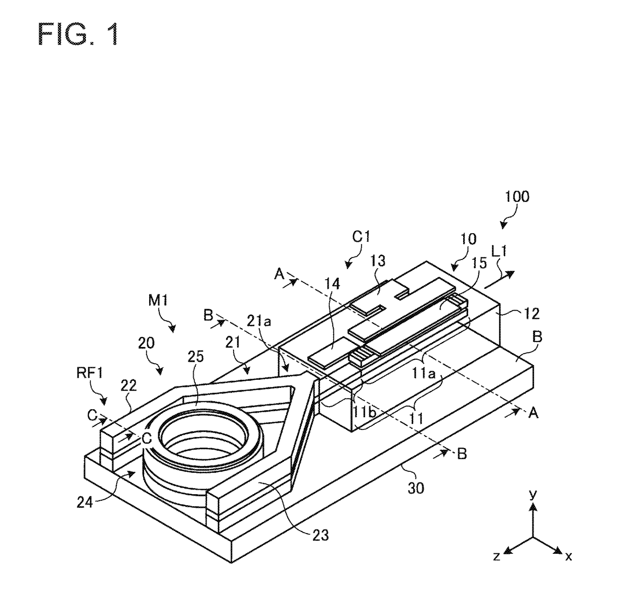
[0045]FIG. 1 is a perspective view schematically illustrating a wavelength tunable laser device according to Embodiment 1. A wavelength tunable laser device 100 is configured to achieve laser oscillation in the 1.55 μm band and output the resulting laser light. The wavelength tunable laser device 100 includes a first waveguide 10 and a second waveguide 20 formed on a common substrate B. The substrate B is made of n-type InP, for example. Moreover, an n-side electrode 30 is formed on the rear surface of the substrate B. The n-side electrode 30 is made of AuGeNi, for example, and is in ohmic contact with the substrate B.
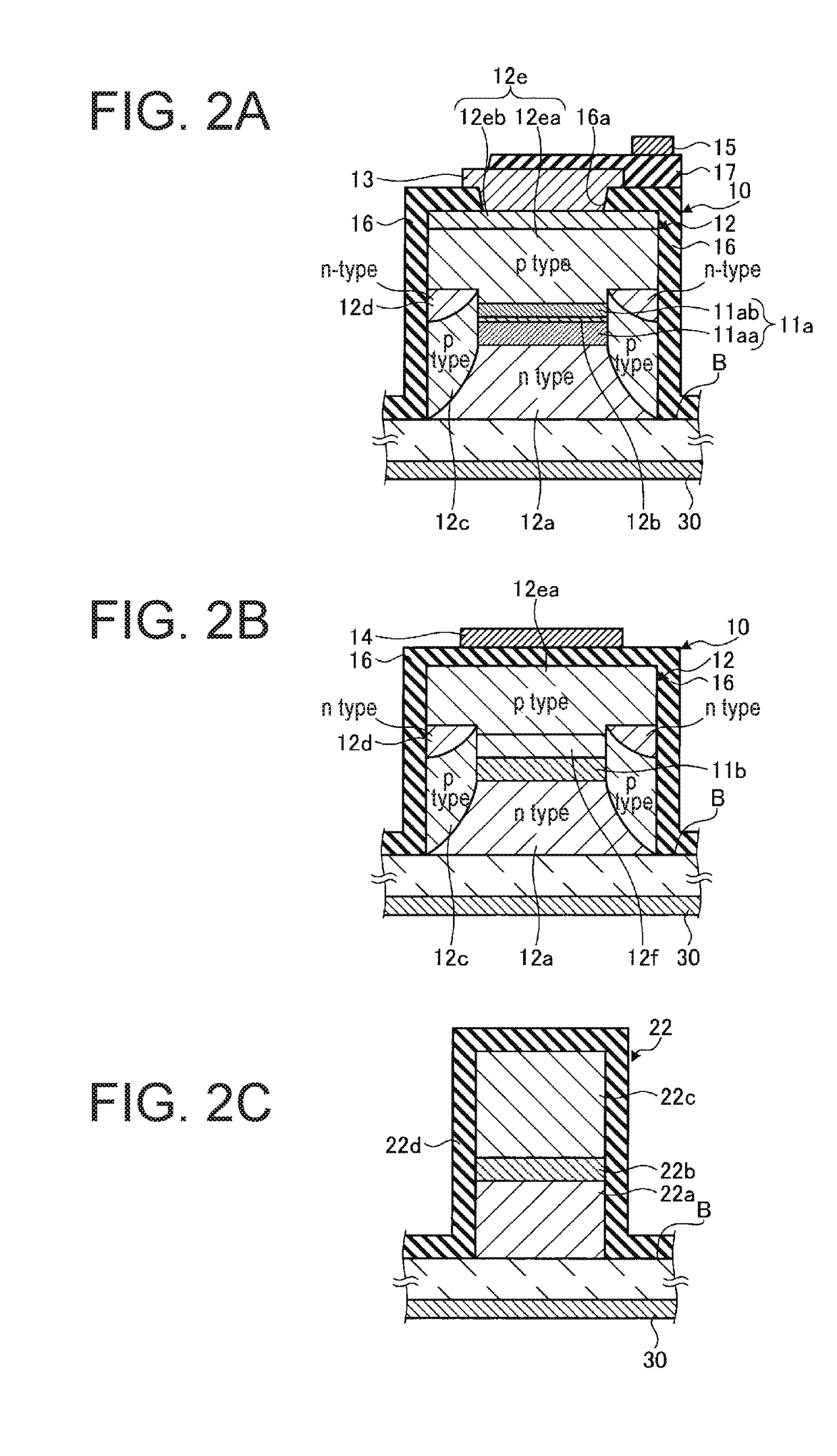
[0046]The first waveguide 10 includes a waveguide 11, a semiconductor stack 12, a p-side electrode 13, and microheaters 14 and 15 made of Ti. The waveguide 11 is formed extending in the Z direction within the semiconductor stack 12. A grating loaded gain portion 11a and a phase adjusting portion 11b are arranged within the first waveguide 10. The semiconductor stack 12...
embodiment 2
[0093]FIG. 11 is a perspective view schematically illustrating a wavelength tunable laser device according to Embodiment 2. As illustrated in FIG. 11, a wavelength tunable laser device 100A according to Embodiment 2 includes the wavelength tunable laser device 100 according to Embodiment 1 as illustrated in FIG. 1 as well as a semiconductor optical amplifier (SOA) 101 formed on a substrate B. The SOA 101 has a buried waveguide structure including an active core layer of the same material and structure as in the first waveguide. Here, however, no grating layer is included.
[0094]The wavelength tunable laser device 100 and the SOA 101 are optically coupled via a spatially coupled optical system (not illustrated in the figure). The laser light L1 output from the wavelength tunable laser device 100 is input to the SOA 101. The SOA 101 optically amplifies the laser light L1 and outputs the resulting light as laser light L2. The wavelength tunable laser device 100A according to Embodiment ...
embodiment 3
[0096]Next, Embodiment 3 will be described. Embodiment 3 is different from Embodiments 1 and 2 in that the second waveguide is a silicon (Si) photonic waveguide, for example.
[0097]FIGS. 12A and 12B schematically illustrate a wavelength tunable laser device according to Embodiment 3. FIG. 12A is a perspective view, and FIG. 12B is a cross-sectional view that will be described later. A wavelength tunable laser device 200 is configured to achieve laser oscillation in the 1.55 μm band and output the resulting laser light. The wavelength tunable laser device 200 includes a first waveguide 210 and a second waveguide 220.
[0098]The first waveguide 210 includes a waveguide 211, a semiconductor stack 212, an n-side electrode 213, and a microheater 215. The waveguide 211 is formed extending in the Z direction within the semiconductor stack 212. A gain portion 211a and a DBR grating layer 211b are arranged within the first waveguide 210. The semiconductor stack 212 is formed by stacking semicon...
PUM
 Abstract
Description
Claims
Application Information
 - R&D
- Intellectual Property
- Life Sciences
- Materials
- Tech Scout
- Unparalleled Data Quality
- Higher Quality Content
- 60% Fewer Hallucinations
Browse by: Latest US Patents, China's latest patents, Technical Efficacy Thesaurus, Application Domain, Technology Topic, Popular Technical Reports.
© 2025 PatSnap. All rights reserved.Legal|Privacy policy|Modern Slavery Act Transparency Statement|Sitemap|About US| Contact US: help@patsnap.com


