
Focused ion beam apparatus

Active Publication Date: 2019-01-08
HITACHI HIGH TECH SCI CORP
View PDF12 Cites 0 Cited by
  • Summary
  • Abstract
  • Description
  • Claims
  • Application Information

AI Technical Summary

Benefits of technology

The invention provides a focused ion beam apparatus that can create a smaller beam diameter by reducing aberration of the condenser lens, and improves the stability of the focused ion beam. This means that the ions emitted from the ion source do not come into contact with the extraction electrode and each electrode configuring the condenser lens, which prevents sputtering and secondary electron generation. As a result, the focused ion beam apparatus performs better and has a longer lifespan than previous versions.

Problems solved by technology

However, outer peripheral components of the ions emitted from the liquid metal ion source do not pass through a hole of the condenser lens, and stay on an electrode surface, which causes a defect.
In addition, in a technology disclosed in Japanese Patent No. 4299074, the extraction electrode and each electrode of the condenser lens are irradiated with the emitted ions, and secondary electrons and sputter particles are generated from the extraction electrode and each electrode of the condenser lens by the irradiation, such that operation of the ion source is unstabilized.
Thus, even if performance of the focused ion beam apparatus is improved, there is a tendency that a stabilizing time of the ion source is shortened.
As such, the strong lens action is less likely to be obtained, control of a beam trajectory is limited, and thus a parallel beam cannot be made.

Method used


Image

  • Focused ion beam apparatus
  • Focused ion beam apparatus
  • Focused ion beam apparatus

Examples


Embodiment Construction

[0022]Hereinafter, illustrative embodiments of the invention will be described with reference to drawings.

[0023]First, an outline of the invention will be described.

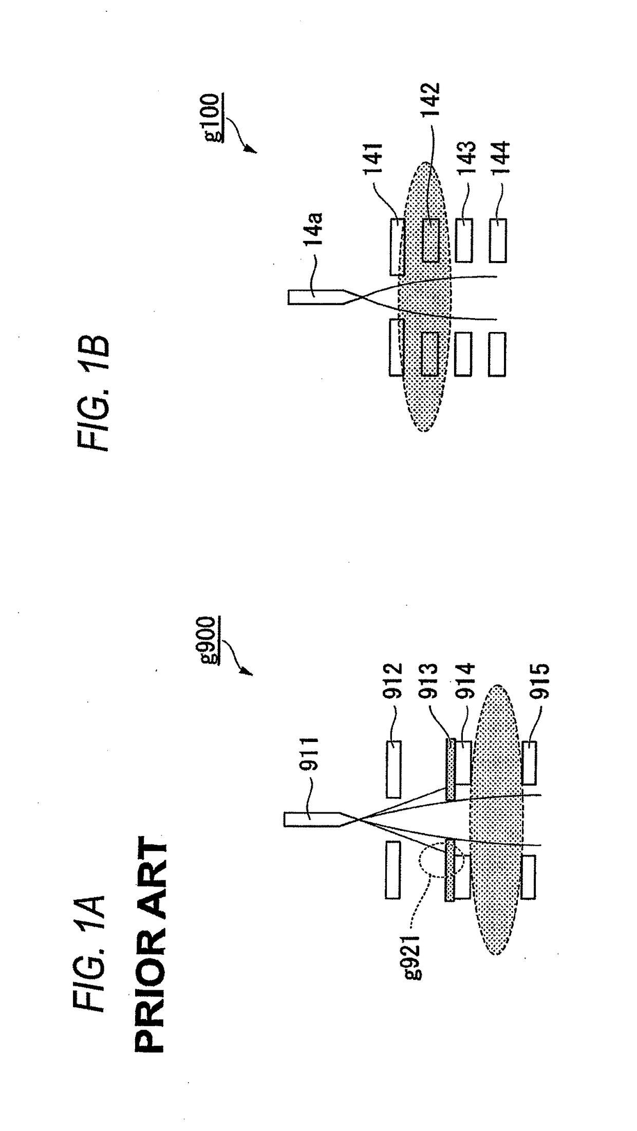
[0024]FIG. 1A is a view illustrating an ion source, a condenser lens, and a trajectory of an ion beam of the related art, and FIG. 1B is a view illustrating an ion source, a condenser lens, and a trajectory of an ion beam of the invention. Also, the condenser lens is a lens which performs controlling of focusing, accelerating, and decelerating of ions emitted from the ion source.

[0025]An image g900 in FIG. 1A is a view illustrating the ion source, the condenser lens, the trajectory of the ion beam of the related art. The image g900 illustrates a part of an ion optical system of the focused ion beam apparatus. The ion source of the related art includes an ion source 911 and an extraction electrode 912. In addition, the condenser lens of the related art includes a fixed diaphragm 913, a first lens electrode 914, and a seco...


PUM


Abstract

A focused ion beam apparatus includes an ion source that emits an ion beam, an extraction electrode that extracts ions from a tip end of an emitter of the ion source, and a first lens electrode that configures a condenser lens by a potential difference with the extraction electrode, the condenser lens focusing the ions extracted by the extraction electrode, in which a strong lens action is generated between the extraction electrode and the first lens electrode so as to focus all ions extracted from the ion source to pass through a hole of the condenser lens including the first lens electrode.

Description

CROSS-REFERENCE TO RELATED APPLICATIONS[0001]This application claims priority from Japanese Patent Application No. 2015-176553 filed on Sep. 8, 2015, the entire subject-matter of which is incorporated herein by reference.TECHNICAL FIELD[0002]The disclosure relates to a focused ion beam apparatus in which a liquid metal ion source is mounted.BACKGROUND[0003]There is a focused ion beam apparatus which processes a predetermined region of a surface of a sample by irradiating the predetermined region of the sample with a focused ion beam while scanning, or observes the surface of the sample by detecting secondary particles generated by irradiation of the focused ion beam.[0004]A liquid metal ion source of the focused ion beam apparatus includes an emitter of which a tip end portion is formed in a needle shape and a surface thereof is wet with a liquid metal. The liquid metal is supplied from a liquid metal supplying source to the tip end portion of the emitter, and a surface thereof is a...

Claims


Application Information

Patent Timeline
IPC IPC(8): H01J37/08H01J37/10H01J37/18
CPCH01J37/08H01J37/10H01J2237/103H01J2237/0805H01J37/18H01J37/12H01J2237/083
Inventor SUGIYAMA, YASUHIKOOBA, HIROSHI
Owner HITACHI HIGH TECH SCI CORP
Learn More