
Compact LIDAR system

a lidar system and compact technology, applied in the field of lidar systems, can solve the problems of reducing the strength of the reflected signal, increasing the difficulty of detecting the source laser, and increasing the interference of simple tof measurements, so as to reduce the linewidth of the source laser, the effect of high linearity and reproducibility

Active Publication Date: 2019-01-01
GM GLOBAL TECH OPERATIONS LLC
View PDF17 Cites 9 Cited by
  • Summary
  • Abstract
  • Description
  • Claims
  • Application Information

AI Technical Summary

Benefits of technology

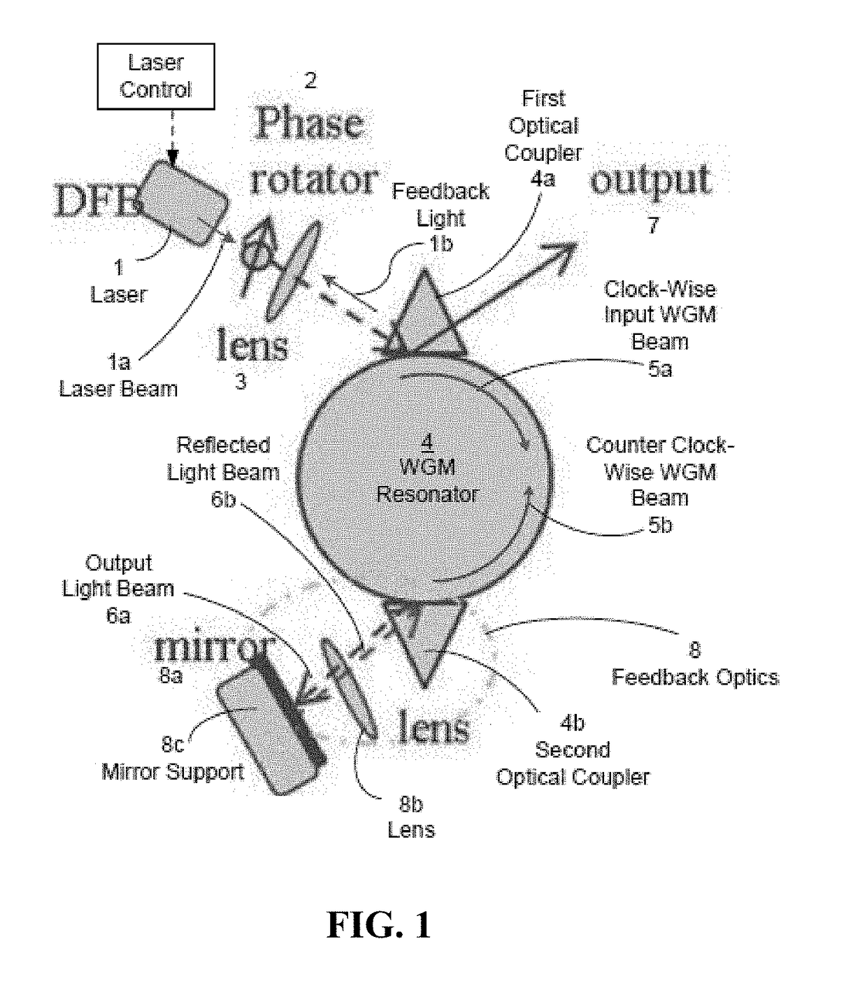
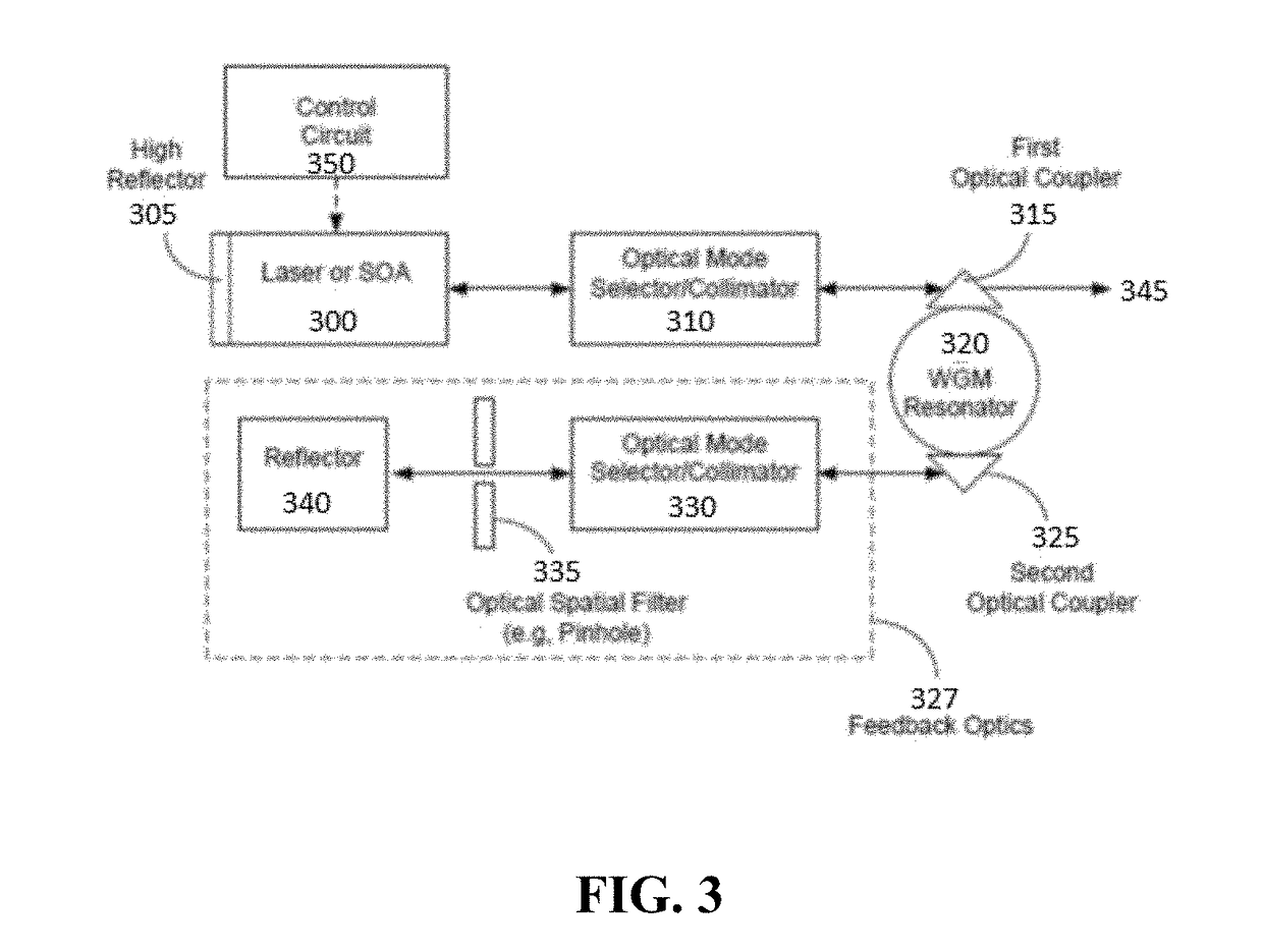
[0011]Embodiments of the inventive concept include a frequency modulated LIDAR system that incorporates a laser source that is optically coupled to a whispering gallery mode optical resonator. Light from the laser that is coupled into the whispering gallery mode optical resonator is coupled back out as a returning counterpropagating wave having a frequency characteristic of a whispering gallery mode of the optical resonator. This returning wave is used to reduce the linewidth of the source laser by optical injection. Modulation of the optical properties of the whispering gallery mode optical resonator results in modulation of the frequency of the frequencies supported by whispering gallery modes of the resonator, and provides a method for producing highly linear and reproducible optical chirps that are highly suited for use in a LIDAR system.

Problems solved by technology

For example, simple TOF measurements are highly susceptible to interference from other signal sources.
This issue becomes more pronounced as the distance between the emitter and the reflecting object increases, as such distance necessarily decreases the strength of the reflected signal.
On the other hand, inherent limitations in accurately measuring extremely short time intervals limit the spatial resolution of such TOF LIDAR systems at close range.
Unfortunately this high degree of sensitivity also leads to increased misidentification of interfering signals as reflect TOF LIDAR pulses.
Unfortunately, improvement in one of these factors is generally at the detriment of the remaining factors.
For example, while increasing the bandwidth of the chirps improves resolution, doing so makes it difficult to maintain linearity of the frequency change within the chirp.
Similarly, lasers that have a narrow linewidth can be poorly suited for production of the range frequencies required to generate a chirp.
In addition, FM LIDAR systems that have been developed to date are far from compact, as they rely on relatively large FMCW laser sources.
As a result FM LIDARs are relatively large, complex, and expensive, and have seen limited implementation relative to TOF LIDARs despite their performance advantages.
The resulting device however, relies on an electronic feedback system that inherently generates nonlinear optical chirps.
The resulting LIDAR source is highly complex, and it remains to be seen if such diverse features can be successfully integrated on a single silicon chip in a reliable fashion.

Method used


Image

  • Compact LIDAR system
  • Compact LIDAR system
  • Compact LIDAR system

Examples


Embodiment Construction

[0026]The following description includes information that may be useful in understanding the present invention. It is not an admission that any of the information provided herein is prior art or relevant to the presently claimed invention, or that any publication specifically or implicitly referenced is prior art.

[0027]The inventive subject matter provides apparatus, systems and methods in which a LIDAR system is based upon a FMCW laser light source that is locked to a whispering gallery mode resonator by optical injection. This provides a laser source with an exceptionally narrow linewidth, which (when used in conjunction with a whispering gallery mode optical resonator having controllable optical properties) permits the generation of large bandwidth, highly linear, and highly reproducible chirps by a simple and direct optical mechanism. Such a frequency modulated (FM) LIDAR does not require the use of a separate local oscillator, but can utilize a beam splitter (or functional equi...


PUM


Abstract

An FM LIDAR system is described that includes a frequency modulated LIDAR system that incorporates a laser source that is optically coupled to a whispering gallery mode optical resonator. Light from the laser that is coupled into the whispering gallery mode optical resonator is coupled back out as a returning counterpropagating wave having a frequency characteristic of a whispering gallery mode of the optical resonator. This returning wave is used to reduce the linewidth of the source laser by optical injection. Modulation of the optical properties of the whispering gallery mode optical resonator results in modulation of the frequency of the frequencies supported by whispering gallery modes of the resonator, and provides a method for producing highly linear and reproducible optical chirps that are highly suited for use in a LIDAR system. Methods of using such an FM LIDAR system and vehicle assisting systems that incorporate such FM LIDAR systems are also described.

Description

[0001]This application claims priority to provisional application No. 62 / 143912 filed Apr. 7, 2015. This and all other referenced patents and applications are incorporated herein by reference in their entirety.FIELD OF THE INVENTION[0002]The field of the invention is LIDAR systems, particularly frequency modulated continuous wave LIDAR systems.BACKGROUND[0003]The background description includes information that may be useful in understanding the present invention. It is not an admission that any of the information provided herein is prior art or relevant to the presently claimed invention, or that any publication specifically or implicitly referenced is prior art.[0004]LIDAR is increasingly used for distance measurement in a variety of applications, ranging from cartography to microscopy. The incorporation of such functionality into an ever-growing range of devices, including autonomous or semi-autonomous vehicles has led to the development of increasingly compact and low power cons...

Claims


Application Information

Patent Timeline
Patent Type & Authority Patents(United States)
IPC IPC(8): G01C3/08G01S17/42G01S17/89G01S17/32G01S17/93G02B6/293H01S3/00G01S7/491G01S7/4911G01S17/34G01S17/931
CPCG01S17/325G01S7/4911G01S17/42H01S3/00G01S17/936G02B6/29341G01S17/89H01S5/0085H01S5/021H01S5/0656H01S5/1032H01S5/142G01S17/34G01S17/931
Inventor MALEKI, LUTFOLLAHMATSKO, ANDREY B.
Owner GM GLOBAL TECH OPERATIONS LLC
Learn More