Two-port SRAM connection structure

Active Publication Date: 2018-12-25
TAIWAN SEMICON MFG CO LTD
View PDF30 Cites 1 Cited by
  • Summary
  • Abstract
  • Description
  • Claims
  • Application Information

AI Technical Summary

Benefits of technology

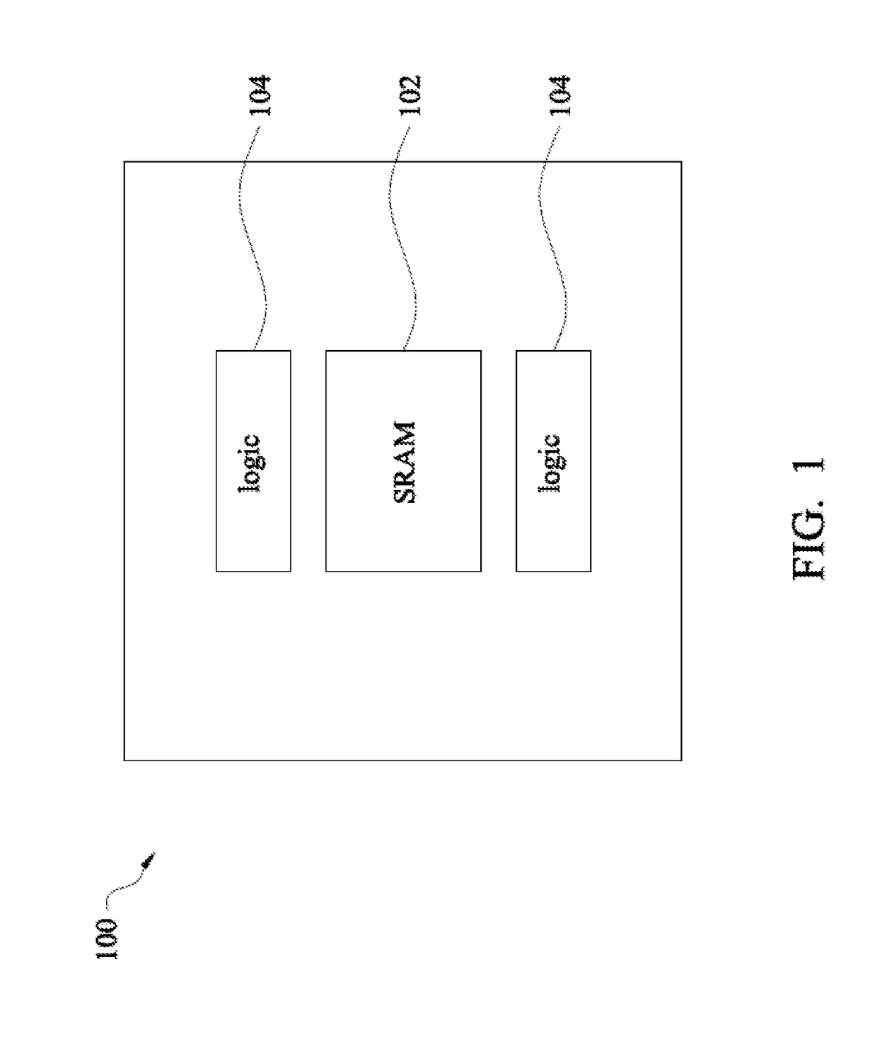
[0016]The present disclosure in various embodiments is generally related to semiconductor devices and methods of forming the same. More particularly, the present disclosure is related to a new and improved jumper structure for use in metal line layers in semiconductor device manufacturing subject to restricted design rules. In embodiments of the present disclosure, the jumper is formed of a conductive metal and, in combination with metal vias in adjoining via layers, provides electrical connection between elements in one or more other metal layers or device layers. For example, two metal lines in a first metal layer may be misaligned, a jumper may be placed in a second metal layer, and metal vias may be formed to electrically connect the jumper to each of the metal lines, thus allowing them to be electrically connected despite their misalignment. The new jumper may be used in multi-layer interconnect formation for integrated circuits (IC) as well as other areas that may be recognized by persons having ordinary skill in the pertinent art. Various aspects of the new jumper are discussed below in the context of multi-layer interconnect formation for an IC 100.

Problems solved by technology

The uni-directional routing rule for metal lines in conjunction with the fixed pitch routing rule may create situations where metal lines cannot be properly aligned between adjoining regions of a chip that are not subject to the same routing rules, e.g., between an SRAM cell region and a peripheral logic region, therefore preventing electrical connection between the two chip regions.

Method used


Image

  • Two-port SRAM connection structure
  • Two-port SRAM connection structure
  • Two-port SRAM connection structure

Examples


Embodiment Construction

[0014]The following disclosure provides many different embodiments, or examples, for implementing different features of the provided subject matter. Specific examples of components and arrangements are described below to simplify the present disclosure. These are, of course, merely examples and are not intended to be limiting. For example, the formation of a first feature over or on a second feature in the description that follows may include embodiments in which the first and second features are formed in direct contact, and may also include embodiments in which additional features may be formed between the first and second features, such that the first and second features may not be in direct contact. In addition, the present disclosure may repeat reference numerals and / or letters in the various examples. This repetition is for the purpose of simplicity and clarity and does not in itself dictate a relationship between the various embodiments and / or configurations discussed.

[0015]F...


PUM

PropertyMeasurementUnit
widthaaaaaaaaaa
packing densityaaaaaaaaaa
speedaaaaaaaaaa

Abstract

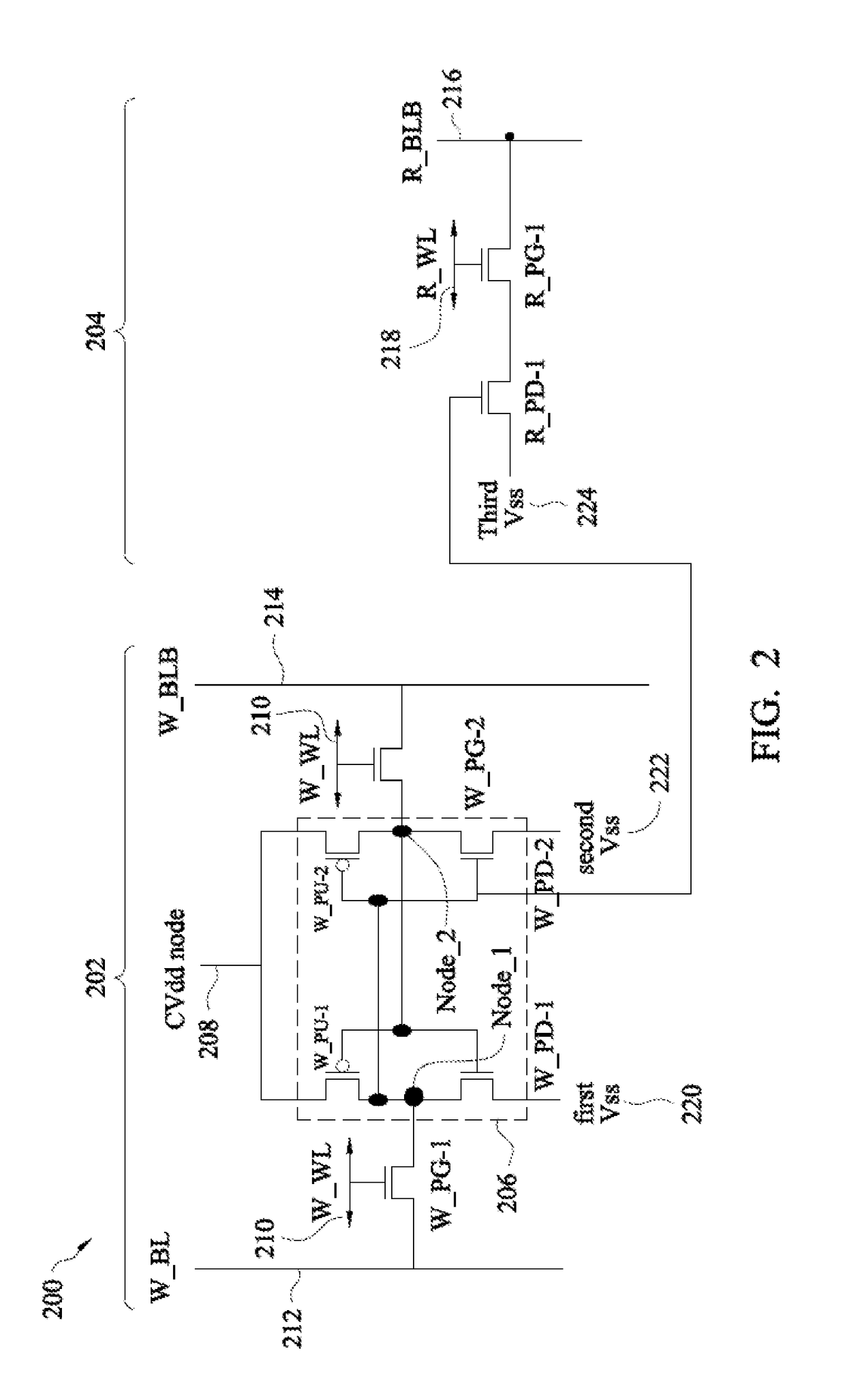
A static random access memory (SRAM) device is provided in accordance with some embodiments. The SRAM device comprises a plurality of two-port SRAM arrays, which comprise a plurality of two-port SRAM cells. Each two-port SRAM cell comprises a write port portion, a read port portion, a first plurality of metal lines located in a first metal layer, a second plurality of metal lines located in a second metal layer, a third plurality of metal lines located in a third metal layer a plurality of edge cells, a plurality of well strap cells, and a plurality of jumper structures. Each jumper structure comprises first, second, and third metal landing pads located in the second metal layer and electrically connecting metal lines of the first and third metal layers.

Description

PRIORITY DATA[0001]The present application is a continuation of U.S. patent application Ser. No. 15 / 253,365, filed Aug. 31, 2016, to Jhon Jhy Liaw, titled “Two-Port SRAM Connection Structure”, which is hereby incorporated by reference in its entirety.BACKGROUND[0002]In deep sub-micron integrated circuit (IC) technology, an embedded static random access memory (SRAM) device has become a popular storage unit of high speed communication, image processing and system-on-chip (SOC) products. For example, a dual port (DP) SRAM device allows parallel operation, such as 1R (read) 1W(write), or 2R (read) in one cycle, and therefore has higher bandwidth than a single port SRAM. In advanced technologies with decreased feature size and increased packing density, low loading and high speed of the cell structure are important factors in embedded memory and SOC products.[0003]As lithography methods used in IC fabrication continually improve to allow smaller and smaller feature sizes to be created i...

Claims


Application Information

Patent Timeline
Patent Type & Authority Patents(United States)
IPC IPC(8): H01L23/528B81B3/00B81C1/00G11C5/06H01L27/11G11C11/419
CPCG11C11/419B81C1/00238B81C1/00246B81C1/00253G11C5/063H01L23/528H01L27/1104H01L27/1116B81B3/0051B81C2203/0778B81B2207/015B81B2207/096B81C2203/0118B81C2203/035B81C2203/0742B81C2203/0764H01L23/48H10B10/00H10B10/12H10B10/18
Inventor LIAW, JHON JHY
Owner TAIWAN SEMICON MFG CO LTD
Why Eureka
Try Eureka