
Thrust washers with hydrodynamic features

a technology of hydrodynamic features and washers, which is applied in the direction of bearings, shafts and bearings, bearings, etc., can solve the problems of failure of thrust washers, achieve the effects of improving the ability to form thin lubricant films, and improving film generation

Active Publication Date: 2018-12-04
FREUDENBERG NOK GEN PARTNERSHIP
View PDF37 Cites 2 Cited by
  • Summary
  • Abstract
  • Description
  • Claims
  • Application Information

AI Technical Summary

Benefits of technology

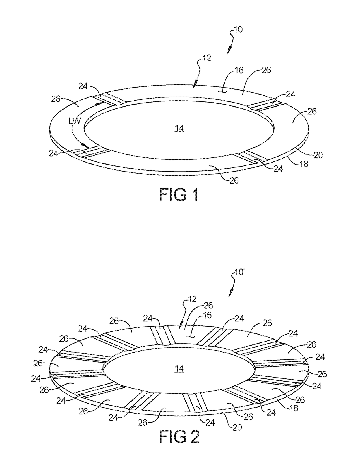
[0003]Thrust washers fail due to loss of lubrication and high interface temperature conditions. This present disclosure uses improved groove features to improve the ability to form thin lubricant films. The features allow better film generation and thereby lower friction and interface temperature. These features allow for use of very low lubrication conditions as they more effectively use the lubricant than conventional groove geometries. The result of these new designs allows them to be used in more aggressive speed and pressure applications while also reducing the torque compared to designs used today.
[0004]The present disclosure is directed to a thrust bearing made from a thermoplastic or thermoset material manufactured using machining or plastic molding techniques. The washer has grooves or partial grooves with the geometric features designed to promote a fluid flow under washer and generate / retain fluid film to support thrust forces and rotational speeds. This results in the washer running at lower friction as it rides on the fluid film generated by the design features.
[0025]With reference to FIG. 8, the plurality of grooves 24 include a lead-in surface 30 having a convex surface 32 defining a lead in radius R1 to generate fluid pressure at the groove inlet 34 and promote formation of a fluid film under the thrust washer along the lands 26. The lead in radius R1 is preferably between 2 mm to 200 mm and more preferably between 2 mm to 50 mm. The lead-in surface 30′ can have an elliptical geometry (FIG. 9) with the major diameter of the ellipse defined by D1 and the minor diameter of the ellipse defined by D2. The elliptical geometry can generate more pressure and create larger fluid film thicknesses. A ratio of the major diameter, D1 to the minor diameter, D2 is preferably in the range of 1.5:1 to 30:1 and more preferably 1.5:1 to 10:1. It has been discovered that the elliptical geometry generates more pressure and creates larger fluid film thicknesses.

Problems solved by technology

Thrust washers fail due to loss of lubrication and high interface temperature conditions.

Method used


Image

  • Thrust washers with hydrodynamic features
  • Thrust washers with hydrodynamic features
  • Thrust washers with hydrodynamic features

Examples


Embodiment Construction

[0018]Example embodiments will now be described more fully with reference to the accompanying drawings.

[0019]Example embodiments are provided so that this disclosure will be thorough, and will fully convey the scope to those who are skilled in the art. Numerous specific details are set forth such as examples of specific components, devices, and methods, to provide a thorough understanding of embodiments of the present disclosure. It will be apparent to those skilled in the art that specific details need not be employed, that example embodiments may be embodied in many different forms and that neither should be construed to limit the scope of the disclosure. In some example embodiments, well-known processes, well-known device structures, and well-known technologies are not described in detail.

[0020]The terminology used herein is for the purpose of describing particular example embodiments only and is not intended to be limiting. As used herein, the singular forms “a,”“an,” and “the” ...


PUM


Abstract

A thrust washer includes an annular body with an aperture therein and having a first axial face and a second axial face, an outer diameter edge and an inner diameter edge extending between the first and second axial faces. At least one of the first and second axial or conical faces includes a plurality of recessed grooves extending at least partially between the inner edge and the outer edge and defining un-recessed lands between the recessed grooves. The plurality of recessed grooves defining an average groove width and the plurality of lands defining an average land width between the grooves, wherein a ratio of the groove width to the land width is in a range of 0.2 to 2. The plurality of recessed grooves include a convex lead in surface having a lead in radius.

Description

FIELD[0001]The present disclosure relates to thrust washers and more particularly, to thrust washers with hydrodynamic features.BACKGROUND AND SUMMARY[0002]This section provides background information related to the present disclosure which is not necessarily prior art.[0003]Thrust washers fail due to loss of lubrication and high interface temperature conditions. This present disclosure uses improved groove features to improve the ability to form thin lubricant films. The features allow better film generation and thereby lower friction and interface temperature. These features allow for use of very low lubrication conditions as they more effectively use the lubricant than conventional groove geometries. The result of these new designs allows them to be used in more aggressive speed and pressure applications while also reducing the torque compared to designs used today.[0004]The present disclosure is directed to a thrust bearing made from a thermoplastic or thermoset material manufac...

Claims


Application Information

Patent Timeline
Patent Type & Authority Patents(United States)
IPC IPC(8): F16C17/04F16C33/10F16C17/10
CPCF16C17/045F16C17/105F16C33/1075F16C33/1065F16C33/107
Inventor SUNDARARAMAN, SAIKRISHNASZPARAGOWSKI, RAYMOND L.BERDICHEVSKY, ALEXANDER
Owner FREUDENBERG NOK GEN PARTNERSHIP
Learn More