
Intra-module DC-DC converter and a PV-module comprising same

a dc-dc converter and pv-module technology, applied in photovoltaic energy generation, single-network parallel feeding arrangement, electric variable regulation, etc., can solve the problems of affecting the overall efficiency, significant power loss, and increasing the eminentity of problems, so as to achieve low input ripple current, high switching frequency operation, and high voltage gain

Active Publication Date: 2018-11-20
KATHOLIEKE UNIV LEUVEN
View PDF7 Cites 3 Cited by
  • Summary
  • Abstract
  • Description
  • Claims
  • Application Information

AI Technical Summary

Benefits of technology

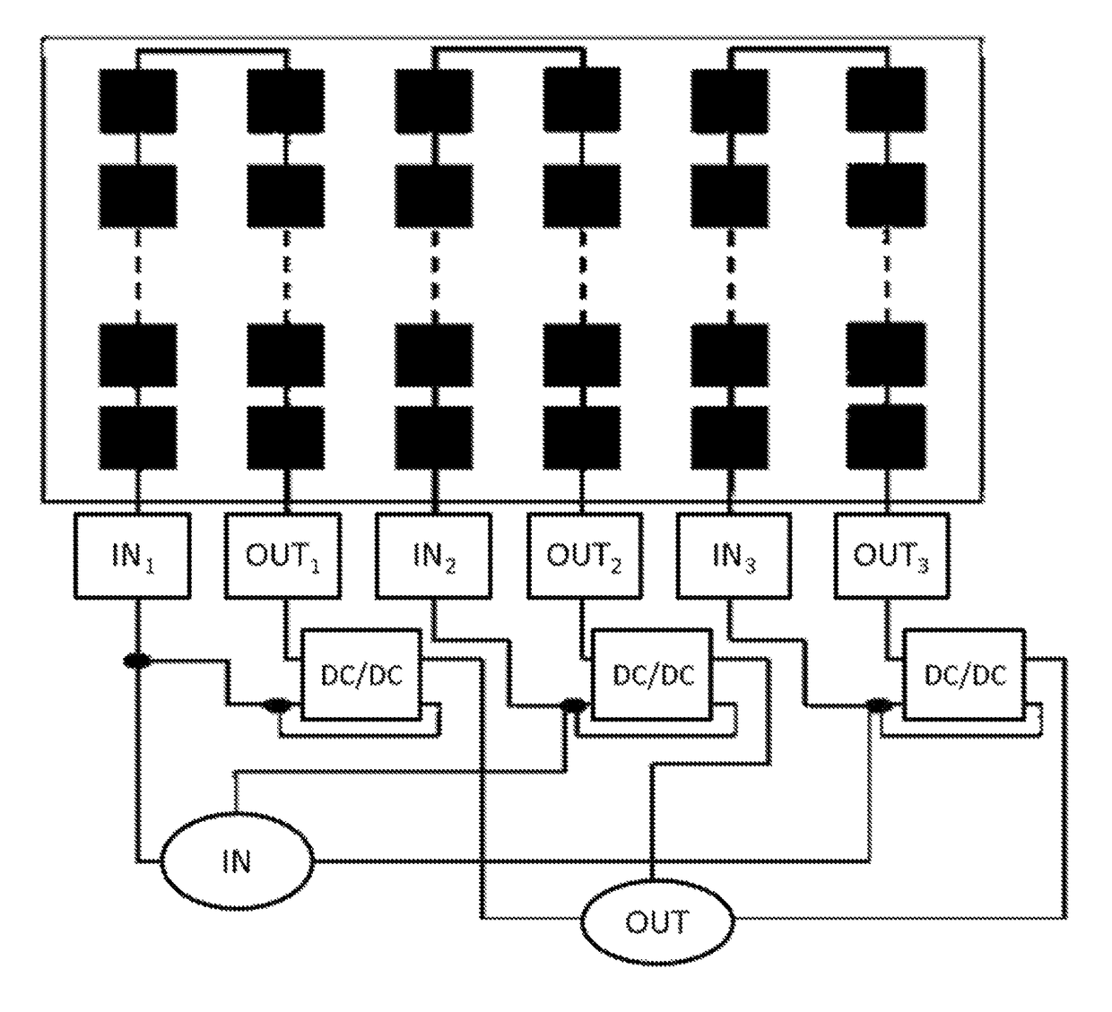
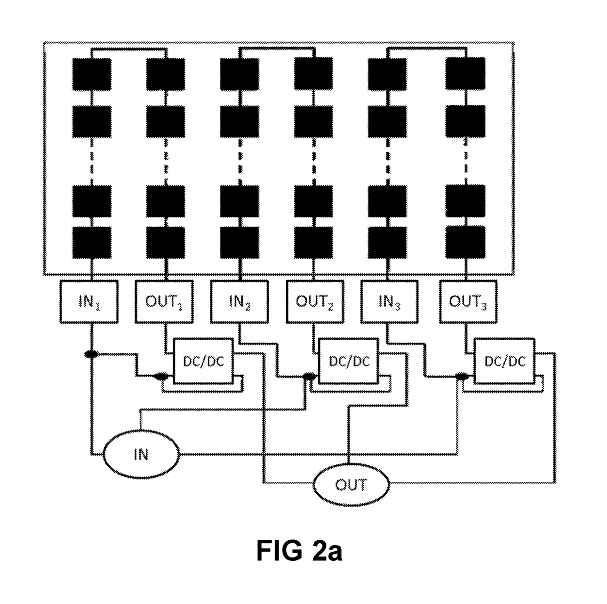
This patent is about a new circuit and method for generating electrical power. The invention improves the efficiency of PV systems. The circuit is designed to operate at high frequency and in a wide input voltage range. It can be used at the string level in PV modules, providing an integrated DC-DC converter. The designed converter has low input ripple current and is suitable for very high switching frequency operations. Overall, the invention provides a good circuit and method for electrical power generation.

Problems solved by technology

In rooftop applications, these problems become more eminent.
These variations in PV cells lead to a relatively significant power loss, which apparently affect the overall efficiency.
The usage of a centralized power converter for a system with a large number of modules, makes this power mismatching a crucial factor.
In state of the art research literature, only limited studies are available on the distributed power management techniques at the PV module and submodule level.
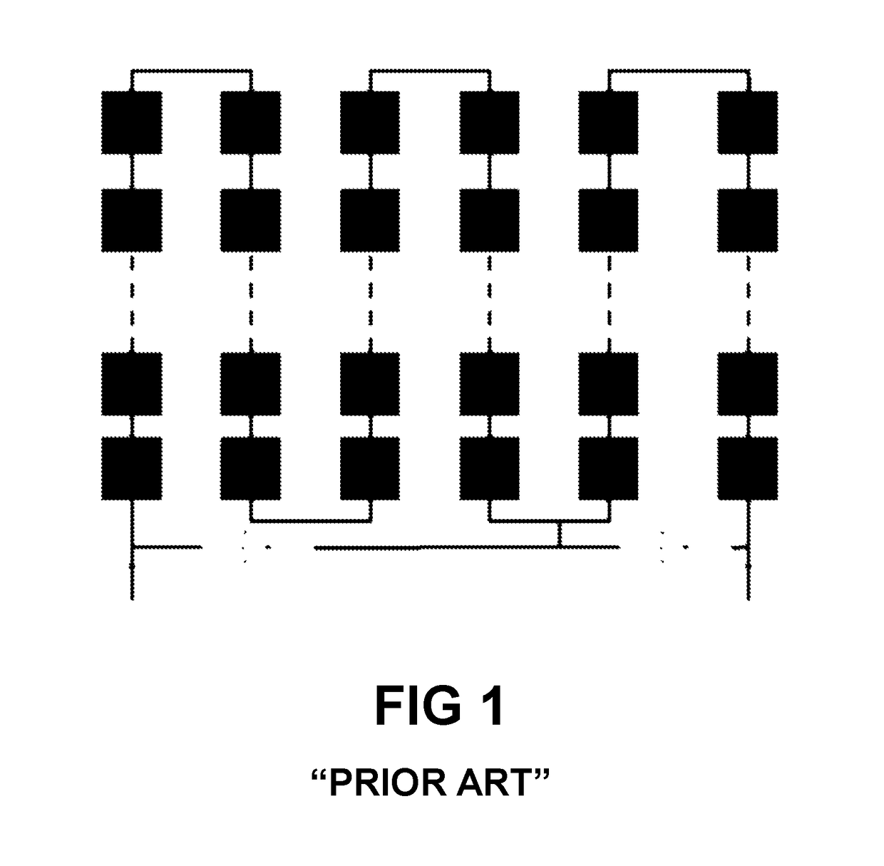
Due to the power mismatch which occurs between different solar cells there is a significant power loss at the output.

Method used


Image

  • Intra-module DC-DC converter and a PV-module comprising same
  • Intra-module DC-DC converter and a PV-module comprising same
  • Intra-module DC-DC converter and a PV-module comprising same

Examples


Embodiment Construction

[0060]The present invention will be described with respect to particular embodiments and with reference to certain drawings but the invention is not limited thereto but only by the claims. The drawings described are only schematic and are non-limiting. In the drawings, the size of some of the elements may be exaggerated and not drawn on scale for illustrative purposes. The dimensions and the relative dimensions do not correspond to actual reductions to practice of the invention.

[0061]Furthermore, the terms first, second and the like in the description and in the claims, are used for distinguishing between similar elements and not necessarily for describing a sequence, either temporally, spatially, in ranking or in any other manner. It is to be understood that the terms so used are interchangeable under appropriate circumstances and that the embodiments of the invention described herein are capable of operation in other sequences than described or illustrated herein.

[0062]Moreover, t...


PUM


Abstract

The present invention relates to an intra-module DC-DC power converter and a Photovoltaic (PV) module comprising same. The switching frequency of said intra-module DC-DC power converters may be 500 kHz. The PV module may have a controller and a plurality of switches for allowing each individual string of said PV module to be connected to one corresponding DC-DC converter, or for allowing two or more strings of said module to be connected in series and to apply the voltage of the combined string to a single DC-DC converter. The input voltage range of the DC-DC converters may be 10V to 30V, and the output voltage range may be 120V. The DC-DC converters may be connected in series or in parallel. Multiple such PV panels may be connected in a DC-grid.

Description

TECHNICAL FIELD[0001]The present invention relates to an intra-module DC-DC converter, and to a PV-module comprising same.TECHNICAL BACKGROUND[0002]Photovoltaic (PV) panels, herein also referred to as PV units or PV modules, have long been argued to be a very attractive solution for future clean energy resource. The efficiency of a photovoltaic system is varied in different operating conditions by time-dependent effects. The efficiency of today's solar panel is about 18% to 23%, however the effective efficiency of a PV system is strongly affected by varying factors such as partial shading. In rooftop applications, these problems become more eminent. In reality, variations in output powers exist between different solar cells of a PV module because of the partial shading in the module. These variations in PV cells lead to a relatively significant power loss, which apparently affect the overall efficiency. The usage of a centralized power converter for a system with a large number of m...

Claims


Application Information

Patent Timeline
Patent Type & Authority Patents(United States)
IPC IPC(8): H02J3/38H02M3/04H02M7/44H02M3/158
CPCH02J3/383H02M3/04H02M7/44H02M3/1584Y02E10/563H02M2003/1586H02J2300/24H02J3/381Y02E10/56H02M3/1586
Inventor CHATTERJEE, URMIMALADRIESEN, JOHAN
Owner KATHOLIEKE UNIV LEUVEN
Learn More