
Wireless power receiving apparatus

a technology of power receiving apparatus and wireless connection, which is applied in the direction of battery data exchange, exchanging data chargers, transportation and packaging, etc., can solve the problem that the abnormal state judgment unit may judge that an abnormal state has occurred, and achieve the effect of uniform characteristics and reduced circuit area

Active Publication Date: 2018-11-13
ROHM CO LTD
View PDF15 Cites 8 Cited by
  • Summary
  • Abstract
  • Description
  • Claims
  • Application Information

AI Technical Summary

Benefits of technology

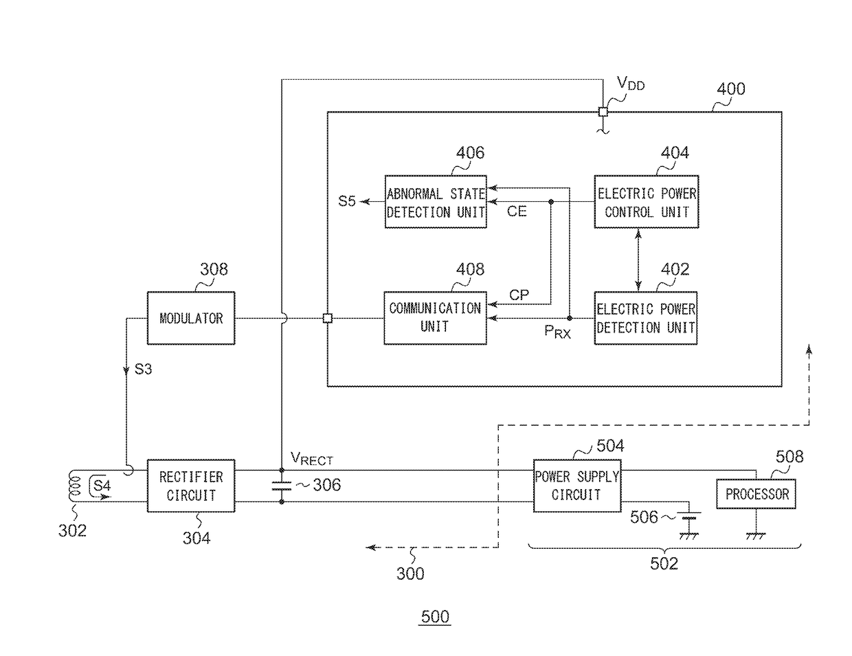
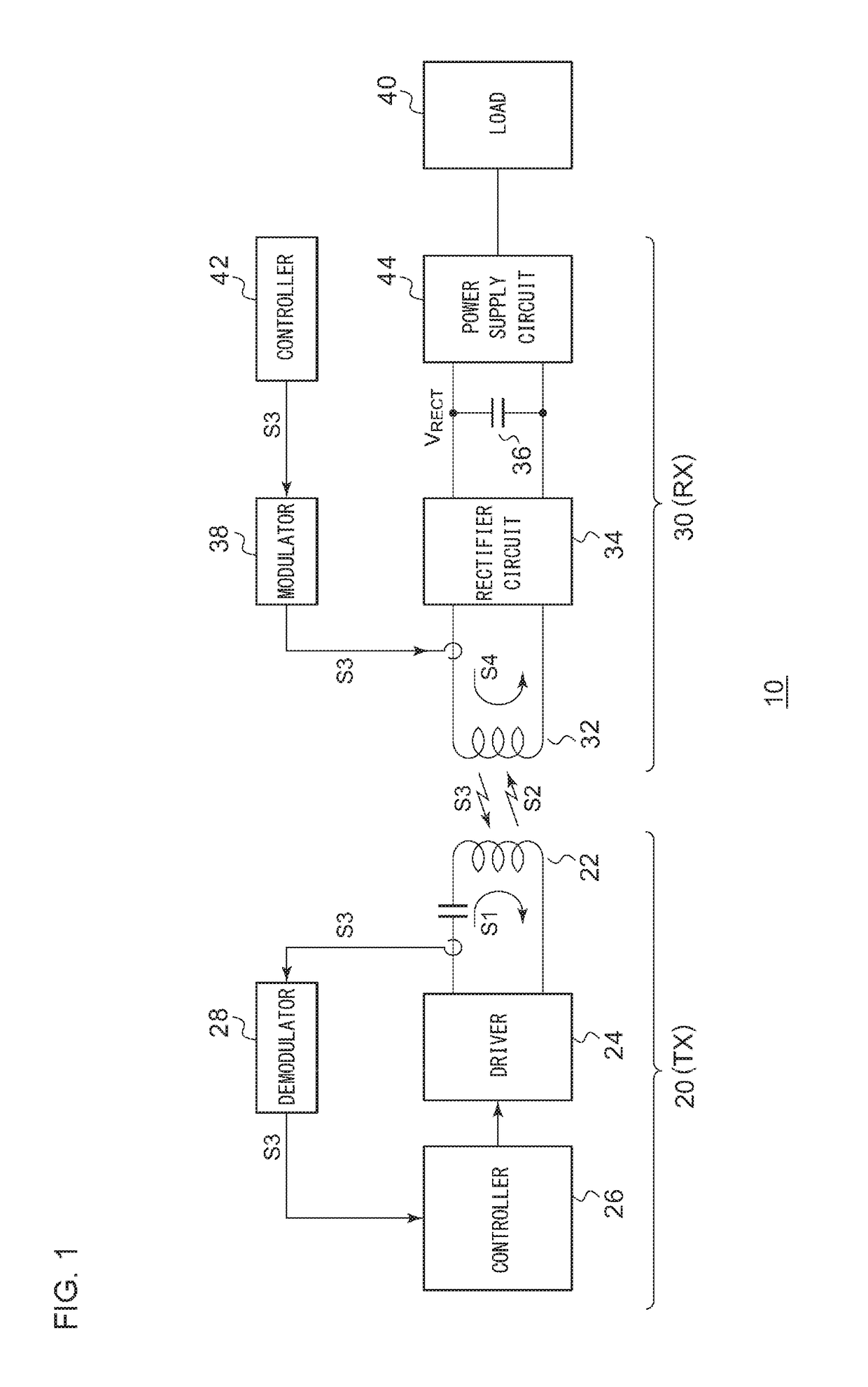
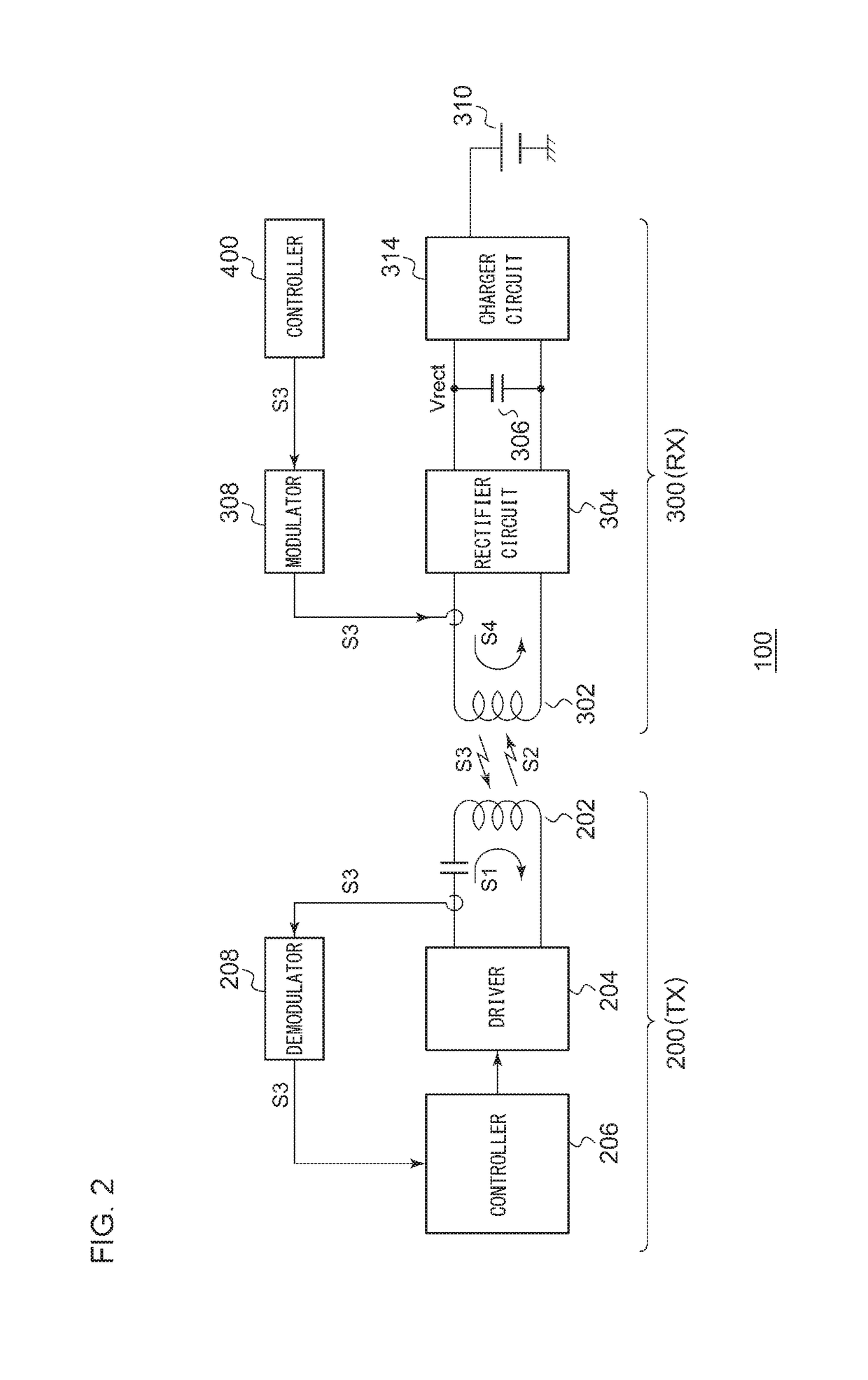
The wireless power transmission apparatus can adjust the level of electric power transmitted based on the information received from the power receiving apparatus. This allows the power receiving apparatus to detect abnormal states based on its own history and the actual power received. This arrangement eliminates the need for a comparison between transmitted and received power, resulting in improved detection precision. Additionally, the received power can be measured with high precision when only the relative value is needed, which removes the effects of noise and facilitates stable abnormal state detection. The patent describes a monolithic arrangement that reduces circuit area and provides uniform circuit characteristics.

Problems solved by technology

Also, when the received electric power detected by the electric power detection unit falls despite the control signal not indicating an instruction to lower the electric power to be transmitted, the abnormal state judgment unit may judge that an abnormal state has occurred.

Method used


Image

  • Wireless power receiving apparatus
  • Wireless power receiving apparatus
  • Wireless power receiving apparatus

Examples


first modification

[First Modification]

[0122]Description has been made in the embodiment regarding an arrangement in which the abnormal state judgment unit 406 judges whether or not an abnormal state has occurred, based on the comparison result between the received electric power PRX detected in the immediately previous step and the received electric power PRX detected in the current step. However, the present invention is not restricted to such an arrangement.

[0123]In a first modification, a threshold value PTH is set based on the received electric power PRX detected in the previous step. Furthermore, judgment is made whether or not an abnormal state has occurred, based on the comparison result between the threshold value PTH and the received electric power PRX detected in the current step.

[0124]The abnormal state judgment unit 406 sets the threshold value PTH based on the measurement values of the received electric power PRX obtained in multiple previous detection steps or otherwise based on the rec...

second modification

[Second Modification]

[0144]In this modification, the power receiving apparatus 300 performs the abnormal state judgment without using the past measurement data of the received electric power PRX. Instead, the power receiving apparatus 300 performs the abnormal state judgment based on the expected value PEX of the received electric power to be received by the power receiving apparatus 300 in the current stage. The common point of the second modification and the embodiment and the first modification is that the past state of the power receiving apparatus 300 is reflected in the expected value PEX.

[0145]The expected value PEX of the received electric power can be estimated based on the expected value of the rectified voltage VRECT, the expected value of the load current ILOAD, etc.

PEX=VCP×ILOAD+VDD×IDD

[0146]Here, VCP represents the expected value of the rectified voltage VRECT, which corresponds to the control point CP.

[0147]The second term of the right-hand side, i.e., VDD×IDD repres...

third modification

[Third Modification]

[0154]In addition to a case in which a foreign object is introduced, in a case in which coil misalignment has occurred, this reduces the coupling coefficient K between the power transmission coil and the power reception coil. This also reduces the received electric power PRX measured by the electric power detection unit 402. Thus, the power receiving apparatus 300 according to the embodiment is applicable to the detection of an abnormal state due to such coil misalignment.


PUM


Abstract

A control circuit is employed for controlling a wireless power receiving apparatus that receives an electric power signal from a wireless power transmission apparatus. An electric power detection unit detects the received electric power PRX received by the wireless power receiving apparatus. A control unit generates a control signal CE for controlling the electric power PTX to be transmitted by the wireless power transmission apparatus. When the received electric power PRX detected by the electric power detection unit falls despite the control signal CE not indicating an instruction to lower the electric power PTX to be transmitted, an abnormal state judgment unit judges that an abnormal state has occurred.

Description

CROSS-REFERENCE TO RELATED APPLICATIONS[0001]This application is a continuation under 35 U.S.C. § 120 of PCT / JP2015 / 051858, filed Jan. 23, 2015, which is incorporated herein reference and which claimed priority to Japanese Application No. 2014-023677, filed Feb. 10, 2014 and Japanese Application No. 2014-111526, filed May 29, 2014. The present application likewise claims priority under 35 U.S.C. § 119 to Japanese Application No. 2014-023677, filed Feb. 10, 2014 and Japanese Application No. 2014-111526, filed May 29, 2014, the entire content of which is also incorporated herein by reference.BACKGROUND OF THE INVENTION[0002]1. Field of the Invention[0003]The present invention relates to a wireless power supply technique, and particularly to a foreign object detection technique.[0004]2. Description of the Related Art[0005]In recent years, in order to supply electric power to an electronic device, contactless power transmission (which is also referred to as “contactless power supply” or...

Claims


Application Information

Patent Timeline
Patent Type & Authority Patents(United States)
IPC IPC(8): H02J7/02H02J50/10H02J50/12H02J50/80H02J50/60H04B5/00H02J5/00H02J50/00
CPCH02J50/60H02J5/005H02J50/80H02J50/10H02J50/12H02J7/025H02J7/00034H02J50/90
Inventor IWASAKI, TATSUYA
Owner ROHM CO LTD
Learn More