
Molten metal rechargeable electrochemical cell

a rechargeable electrochemical cell and molten metal technology, applied in the direction of cell components, electrochemical generators, jackets/cases materials, etc., can solve the problems of complex and inefficient cell configuration, effective sealing and anti-corrosion measures, and many significant technical drawbacks of traditional molten electrode electrochemical cells, so as to reduce cost, reduce chemical reactivity, and high commercial availability

Active Publication Date: 2018-11-13
EOS ENERGY TECH HLDG LLC
View PDF18 Cites 1 Cited by
  • Summary
  • Abstract
  • Description
  • Claims
  • Application Information

AI Technical Summary

Benefits of technology

The solution results in electrochemical cells with reduced costs, increased safety, and improved performance characteristics, including higher commercial availability and lower chemical reactivity, allowing for the production of non-hermetically sealed cells and batteries with enhanced energy storage capabilities.

Problems solved by technology

These traditional molten electrode electrochemical cells suffer from a number of substantial technical drawbacks.
In turn, this necessitates complicated and inefficient cell configurations that are required to form useful batteries.
Moreover, technical problems (e.g., effective sealing and anti-corrosion measures) arise from the manufacture of cells that are airtight at elevated temperatures.
Solutions to these technical problems add to system design complexity and increased cell construction costs.
Traditional molten electrode cells are also limited by reduced performance characteristics.
For example, many traditional molten cells generate undesirably low voltages (e.g., less than 1 V).
And, in other traditional cells, the anode material, the cathode material, or both comprise environmentally harmful, toxic, or otherwise expensive metals.

Method used


Image

  • Molten metal rechargeable electrochemical cell
  • Molten metal rechargeable electrochemical cell
  • Molten metal rechargeable electrochemical cell

Examples


example 1

hode Cells

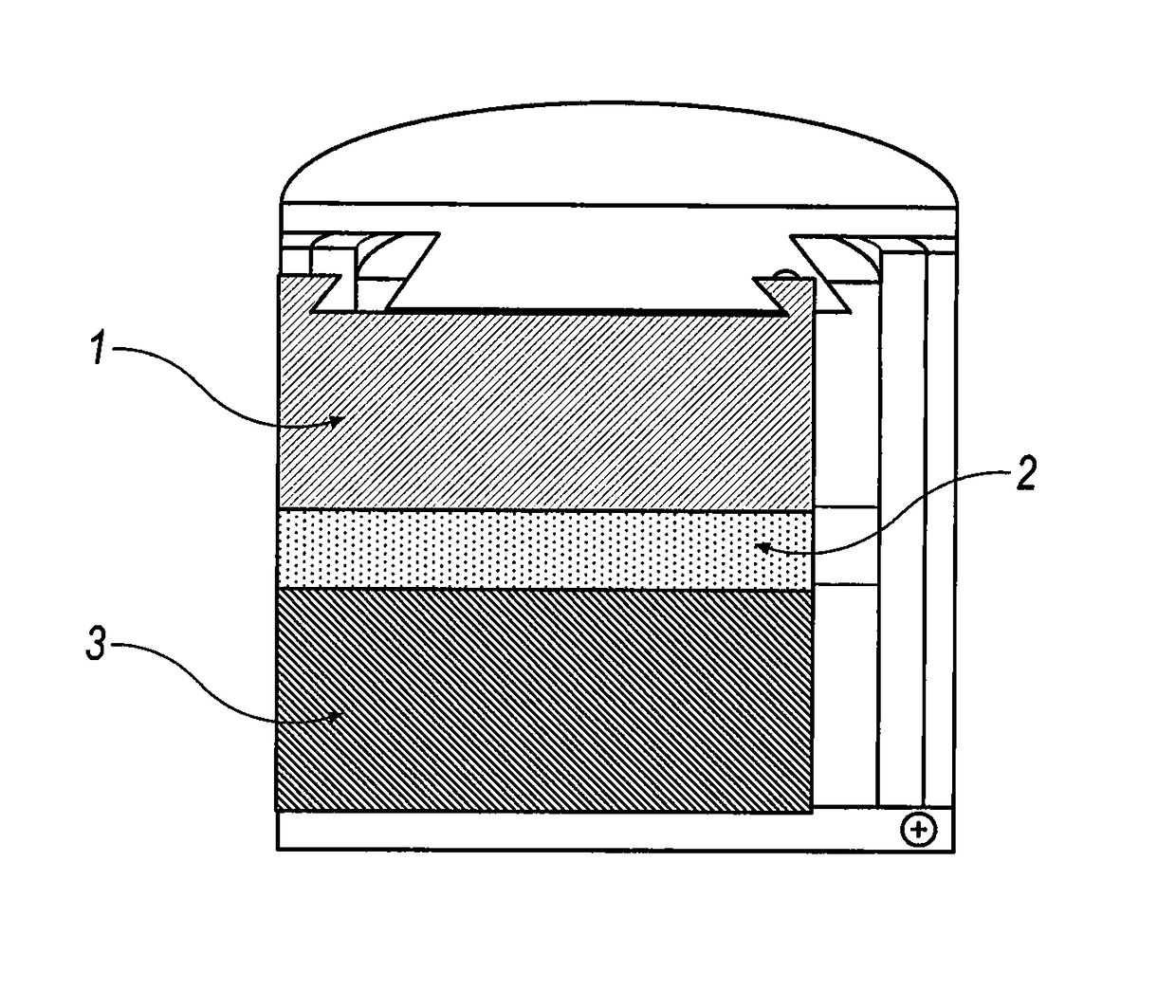
[0154]Five cells according to the present invention were formed using a Kerr Auto Electro-Melt furnace that was modified to include two holes in the cover to allow for the insertion of current collectors into the anode and cathode. The Kerr Auto Electro-Melt furnace included a graphite crucible placed on the inside of the furnace. Within the graphite crucible, an alumina crucible (33 mm outer diameter, 25 mm inner diameter, 105 mm length—McDanel Ceramics) was placed. The materials used for the molten metal battery were placed inside of the alumina crucible. 10 g of the cathode material (50 / 50 weight mixture of bismuth and tin granules (1-2 mm)) was first placed in the alumina crucible. 15 g of the electrolyte (a powder combination of 18% wt NaF, 48% wt AlF3, 16% wt CaF2, and 18% wt BaF2 that has already been mixed, heated to melting in alumina crucible using a muffle furnace at 900° C., then allowed to cool and solidify) was then placed in the alumina crucible. Then, 10 g ...

example 2

Cathode Cell

[0207]An example cell of the present invention was constructed according to the procedures described in Example 1, using 10 g of tungsten oxide (WO3) for the cathode material.

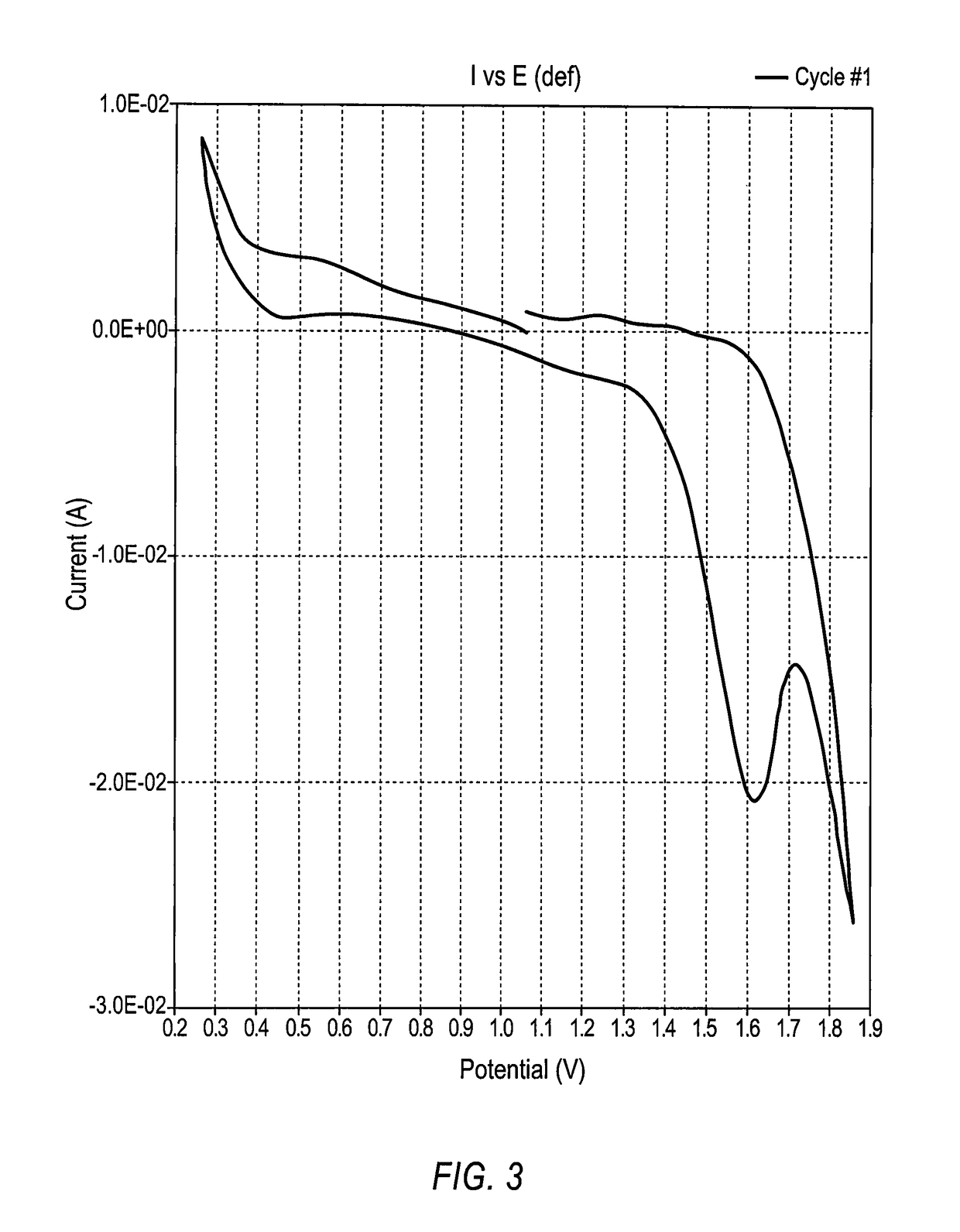
[0208]In the CV scan, i.e., the I vs. E plot, depicted in FIG. 9, the scan potentials ranged from 0.5 V (discharge voltage) to 1.8 V. This cell generated peak discharge currents at 0.5 V that were >9 mA / cm2.


PUM

PropertyMeasurementUnit
operating temperatureaaaaaaaaaa
voltagesaaaaaaaaaa

Abstract

The present invention provides rechargeable electrochemical cells comprising a molten anode, a cathode, and a non-aqueous electrolyte salt, wherein the electrolyte salt is situated between the molten anode and the cathode during the operation of the electrochemical cell, and the molten anode comprises an aluminum material; also provided are batteries comprising a plurality of such rechargeable electrochemical cells and processes for manufacturing such rechargeable electrochemical cells.

Description

CROSS REFERENCE TO RELATED APPLICATION[0001]This U.S. patent application claims the benefit of U.S. provisional application Ser. Nos. 61 / 843,464, filed on Jul. 8, 2013, and 61 / 988,460, filed on May 5, 2014. The entire contents of these patent applications are incorporated herein by reference in their entireties.FIELD OF THE INVENTION[0002]This invention generally relates to electrically rechargeable electrochemical cells and batteries; specifically, electrochemical cells and batteries that employ molten electrode materials.BACKGROUND[0003]There has been considerable recent interest in the subject of elevated temperature molten liquid metal batteries for stationary electrical storage. This low cost energy storage technology holds promise to safely store highly intermittent renewable energy sources such as solar and wind energy. This will help meet increasing global electricity demand while simultaneously reducing CO2 greenhouse emissions. These rechargeable (secondary) batteries cons...

Claims


Application Information

Patent Timeline
Patent Type & Authority Patents(United States)
IPC IPC(8): H01M10/39H01M2/10H01M4/38H01M4/46H01M4/66H01M10/615H01M2/02H01M50/117
CPCH01M10/399H01M2/0252H01M2/0257H01M2/1088H01M4/38H01M4/661H01M4/663H01M10/615H01M4/463H01M2300/0054H01M2300/0048Y02E60/10H01M50/138H01M50/117
Inventor AMENDOLA, STEVENSHARP-GOLDMAN, STEFANIE
Owner EOS ENERGY TECH HLDG LLC
Learn More