
Window vent stop with plastic spring member for bi-directional biasing of the tumbler

a technology of bi-directional biasing and window vent stop, which is applied in the direction of wing accessories, door/window fittings, carpet fasteners, etc., can solve the problems of double hung windows that are opened wide, unauthorized ingress and egress from the premises, and the side of the fully opened position to be a source of danger for small children

Active Publication Date: 2018-10-23
VISION INDS GROUP
View PDF422 Cites 5 Cited by
  • Summary
  • Abstract
  • Description
  • Claims
  • Application Information

AI Technical Summary

Benefits of technology

The present invention provides a vent stop that is easier to install than previous versions and is more reliable in its operation. It is adaptable to a variety of window types and sizes, and can fit into a range of recesses carved into a window frame. The housing has flexible side engagement pieces that help in the installation process.

Problems solved by technology

While a fully opened position can be desirable for ventilation purposes there can be a downside to the fully opened position.
One downside is security.
A fully open window or door, however, can be a location for unauthorized ingress and egress from the premises.
For example, a double hung window that is opened wide can be a source of danger to small children who may climb up to the window.
One particular problem encountered, however, by users of window vent stops is that the installation becomes a difficult process.
Problems occur when a mold of the window vent stop to be installed is used to carve the recess.
At times due to mistakes by the person installing or the inaccuracies of the mold used to carve the recess, the recess cut into the sash stile is often not exactly a perfect fit for the vent stop, whether it be too large or too small.
Another problem with the prior art vent stops, is that if a user wants a particular vent stop, that user must purchase a vent stop that is specifically fit for the sash stile thickness of that user's windows.

Method used


Image

  • Window vent stop with plastic spring member for bi-directional biasing of the tumbler
  • Window vent stop with plastic spring member for bi-directional biasing of the tumbler
  • Window vent stop with plastic spring member for bi-directional biasing of the tumbler

Examples


Embodiment Construction

[0050]As used throughout this specification, the word “may” is used in a permissive sense (i.e., meaning having the potential to), rather than the mandatory sense (i.e., meaning must). Similarly, the words “include”, “including”, and “includes” mean including but not limited to.

[0051]The phrases “at least one”, “one or more”, and “and / or” are open-ended expressions that are both conjunctive and disjunctive in operation. For example, each of the expressions “at least one of A, B and C”, “one or more of A, B, and C”, and “A, B, and / or C” mean all of the following possible combinations: A alone; or B alone; or C alone; or A and B together; or A and C together; or B and C together; or A, B and C together.

[0052]Also, the disclosures of all patents, published patent applications, and non-patent literature cited within this document are incorporated herein in their entirety by reference.

[0053]Furthermore, the described features, advantages, and characteristics of any particular embodiment ...


PUM


Abstract

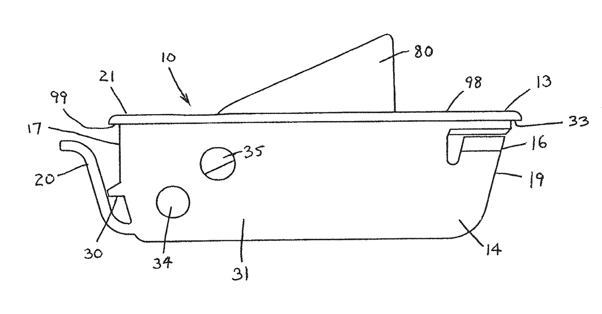
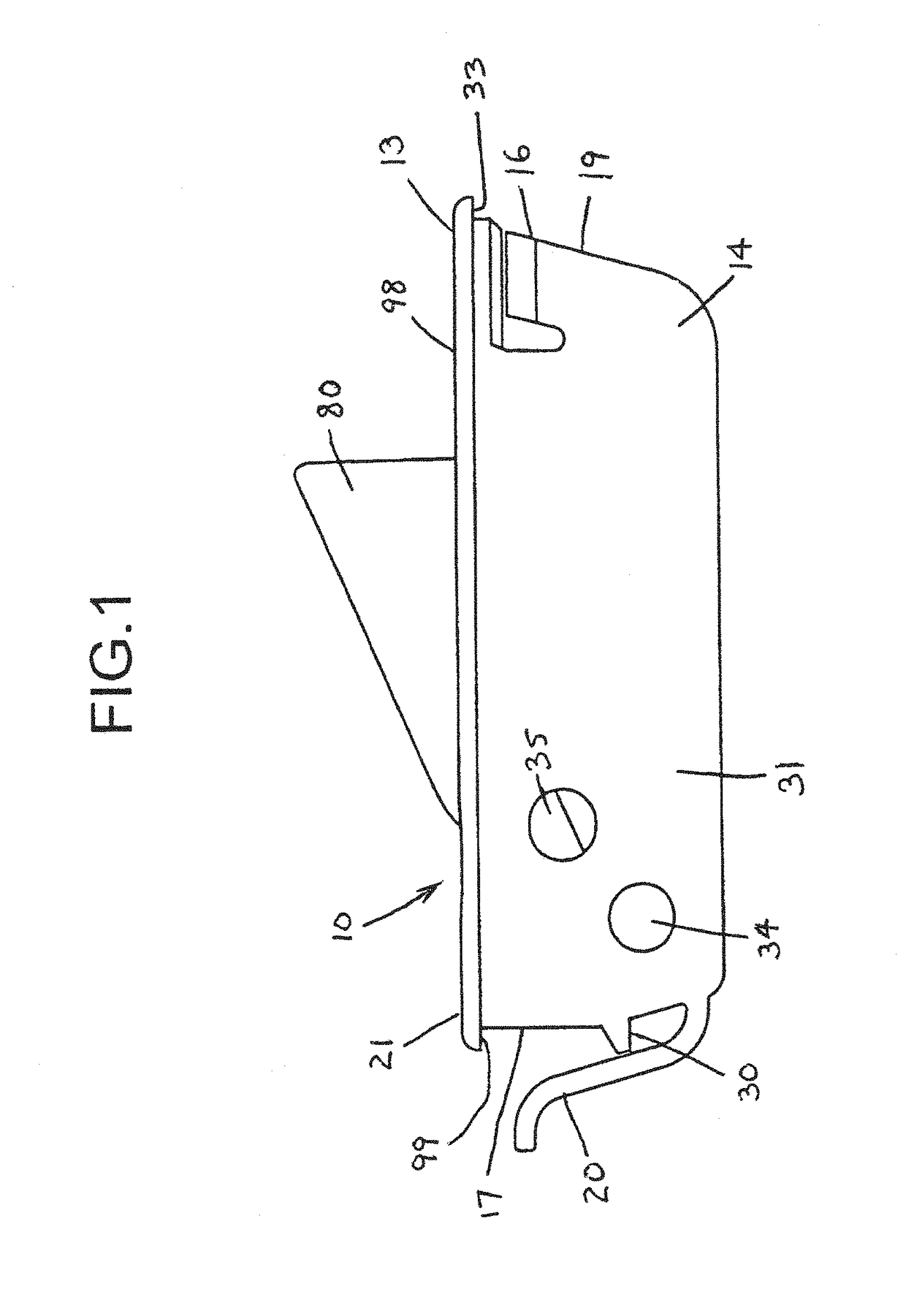
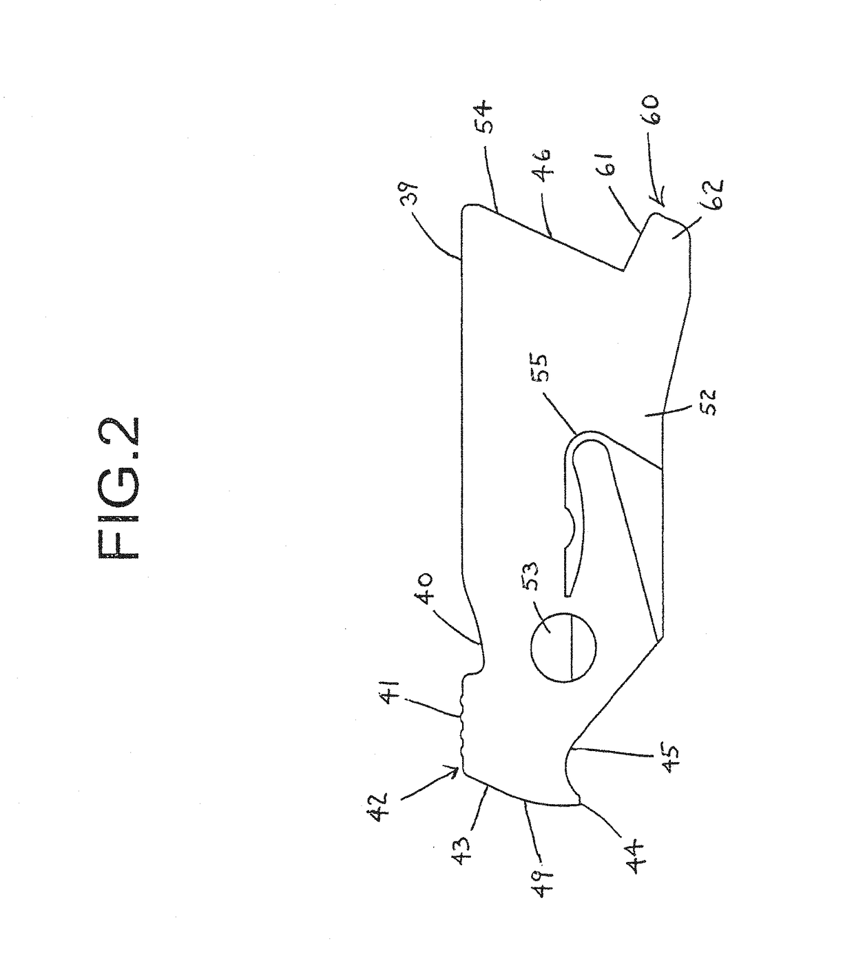
A window vent stop for use in a sliding sash window or a sliding door assembly. The vent stop has a housing adapted to be disposed in a recess in the non-movable sash member. This housing includes a cavity with a bottom plate therein. The tumbler has at least one pivot for pivotally securing the tumbler to the housing for movement between an extended position, to prevent movement of the sliding member and a retracted position, to allow movement of the sliding member. Also within the housing the tumbler is formed with a plastic member for selectively biasing the tumbler. The housing has one or more flexible members extending from the end walls of the housing that secure the housing to an opening in a window sash when a portion of the window sash is positioned between the underside of a lip on the housing and the flexible member.

Description

CROSS REFERENCES TO RELATED APPLICATIONS[0001]This application is a continuation-in-part of U.S. application Ser. No. 15 / 484,295, filed on Apr. 11, 2017, which is a continuation of U.S. application Ser. No. 15 / 471,158, filed Mar. 28, 2017, which is a continuation of U.S. application Ser. No. 14 / 198,949, filed Mar. 6, 2014, which is a continuation of U.S. application Ser. No. 12 / 658,642, filed Feb. 9, 2010, now issued as U.S. Pat. No. 8,833,809, which is a divisional of U.S. application Ser. No. 11 / 977,445, filed Oct. 24, 2007, now issued as U.S. Pat. No. 8,235,430, which is a continuation-in-part of U.S. application Ser. No. 11 / 390,467, filed Mar. 28, 2006, now issued as U.S. Pat. No. 7,530,611, all disclosures of which are incorporated herein by reference.FIELD OF THE INVENTION[0002]The present invention relates to improved window vent stops particularly for double hung windows and the like and to improvements in their operation. These window vent stops are used to prevent a window...

Claims


Application Information

Patent Timeline
Patent Type & Authority Patents(United States)
IPC IPC(8): E05C17/60E05B9/08E05B15/00E05C3/14E06B7/02E05B65/08E05B15/04
CPCE06B7/02E05B65/0811E05C3/14E05B9/08E05B15/0053E05C17/60Y10S292/47Y10S292/31E05B2015/0496E05B65/0835E05C3/04E05B2015/0468
Inventor LIANG, LUKELIANG, TONGCHEN, DAVID
Owner VISION INDS GROUP
Learn More