Electron spin resonance apparatus

a technology of electron spin and resonance apparatus, which is applied in the direction of magnetic measurement, instruments, measurement devices, etc., can solve the problem of changing the repeating frequency of the pulse sequence, and achieve the effect of accurate repeating of the pulse sequen

Active Publication Date: 2018-07-31
JEOL LTD
View PDF3 Cites 1 Cited by
  • Summary
  • Abstract
  • Description
  • Claims
  • Application Information

AI Technical Summary

Benefits of technology

[0018]An advantage of the present invention is that the lock-in demodulation is enabled without changing the frequency used in the lock-in demodulation even when the repetition frequency of the pulse sequence is changed in an electron spin resonance apparatus. An alternative advantage of the present invention is that the pulse sequence is repeated accurately.
[0019]According to one aspect of the present invention, there is provided an electron spin resonance apparatus comprising: a microwave generator that generates a microwave signal; a pulse train signal generator that generates a pulse train signal according to a modulation frequency Fm and a repetition frequency Fp of a pulse sequence; an excitation signal generator that applies the pulse train signal on the microwave signal to generate an excitation signal; an electron spin resonance chamber that houses a sample and to which the excitation signal is sent; and a demodulator that executes a lock-in demodulation using the modulation frequency Fm on a detection signal reflecting electron spin resonance caused in the sample, to generate an analysis target signal, wherein the repetition frequency Fp and the modulation frequency Fm are in a relationship Fp=2n×Fm, wherein n is an integer greater than or equal to 1.
[0020]According to the above-described configuration, a pulse train signal according to a modulation frequency Fm and a repetition frequency Fp is applied to a microwave signal, to generate an excitation signal. The excitation signal is used to excite an electron spin resonance. A detection signal reflecting the electron spin resonance changes synchronously with the modulation frequency Fm (that is, according to the frequency component of Fm). Thus, lock-in demodulation is executed using the modulation frequency Fm on the detection signal. In the above-described configuration, the repetition frequency Fp of the pulse sequence is not used for the lock-in demodulation, and the modulation frequency Fm is used for the lock-in demodulation. In other words, the modulation frequency Fm which is different from the repetition frequency Fp which defines the repetition of the pulse sequence is used for the lock-in demodulation, and thus, even when the repetition frequency Fp is changed, the lock-in demodulation can be executed without changing the modulation frequency Fm.
[0021]In addition, in the above-described configuration, the repetition frequency Fp and the modulation frequency Fm are in the relationship of Fp=2n×Fm. In other words, the repetition frequency Fp is an even-number multiple of the modulation frequency Fm. For example, the repetition frequency Fp and the integer n are changed according to the sample and the measurement details. By satisfying the above-described relationship, it becomes possible not to include a fractional pulse sequence in the pulse train signal according to the modulation frequency Fm, and to accurately repeat the pulse sequence according to the repetition frequency Fp.
[0022]The above-described electron spin resonance apparatus is used, for example, for detection methods such as the longitudinally detected ESR, the electrically detected magnetic resonance, the optically detected magnetic resonance, or the like. Alternatively, the above-described electron spin resonance apparatus may be applied to other detection methods.
[0023]According to another aspect of the present invention, there is provided an electron spin resonance apparatus comprising: a microwave generator that generates a microwave signal; a pulse train signal generator that generates a pulse train signal in which a reference pulse train is repeated with a repetition frequency Fp and which is modulated by a modulation signal having a modulation frequency Fm; an excitation signal generator that modulates the microwave signal with the pulse train signal to generate an excitation signal; an electron spin resonance chamber that houses a sample and to which the excitation signal is supplied; a detector that generates a detection signal reflecting electron spin resonance caused in the sample; and a demodulator that executes a lock-in demodulation on the detection signal based on the modulation signal, to generate an analysis target signal, wherein the repetition frequency Fp and the modulation frequency Fm are in a relationship Fp=2n×Fm, wherein n is an integer greater than or equal to 1, and the repetition of the reference pulse train and the modulation by the modulation signal are synchronous with each other.

Problems solved by technology

In a method in which the irradiation of the microwave pulse and the lock-in demodulation are combined such as the hybrid ESR described above, a problem may arise when the repetition frequency of the pulse sequence is changed.

Method used


Image

  • Electron spin resonance apparatus
  • Electron spin resonance apparatus
  • Electron spin resonance apparatus

Examples


first preferred embodiment

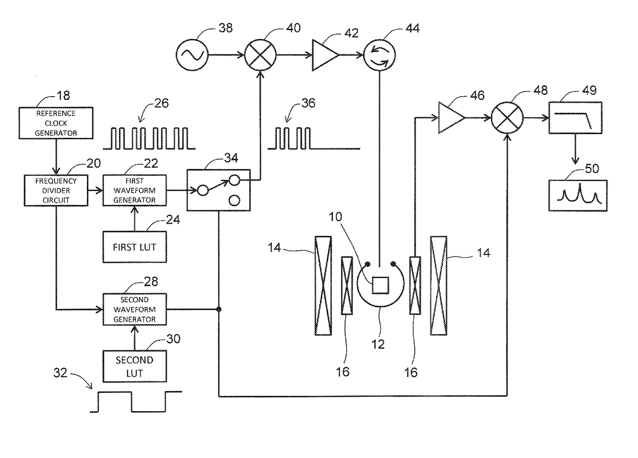
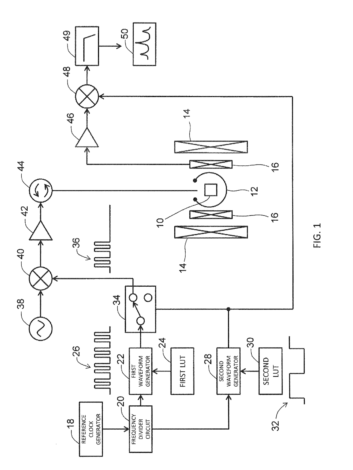
[0047]FIG. 1 shows an example electron spin resonance apparatus (ESR apparatus) according to a first preferred embodiment of the present invention. The ESR apparatus is an apparatus that realizes the longitudinally detected ESR (LOD-ESR). The ESR apparatus according to the first preferred embodiment excites electron spin resonance by a modulated microwave, and detects a longitudinally detected ESR signal (LOD-ESR signal) by phase demodulation (lock-in demodulation).

[0048]A sample tube having a sample 10 placed inside is inserted into a microwave resonator 12. The sample 10 may be any of gas, solid, and liquid. The microwave resonator 12 is placed between two electromagnets 14. With this configuration, the microwave resonator 12 is placed in a static magnetic field generated by the electromagnets 14. In addition, a pickup coil 16 having a wiring axis placed in a direction parallel to the static magnetic field is placed near the sample 10. In some cases, a coolant such as helium may b...

second embodiment

[0084]FIG. 5 shows an example ESR apparatus according to a second preferred embodiment of the present invention. This ESR apparatus is an apparatus that realizes the electrically detected magnetic resonance (EDMR). The ESR apparatus of the second preferred embodiment excites electron spin resonance by a modulated microwave, and detects the EDMR signal by lock-in demodulation.

[0085]In the second preferred embodiment, a current (voltage) is applied to the sample 10 by a voltage supply and detection device 52. In the second preferred embodiment also, the original pulse train 26 is modulated according to the modulation frequency Fm of the modulation signal 32, and, with this process, the pulse train signal 36 is generated. Similar to the first preferred embodiment, the repetition frequency Fp and the modulation frequency Fm are in the relationship Fp=2n×Fm.

[0086]A microwave generated by the microwave oscillator 38 is modulated by the pulse train signal 36, and, with this process, an exc...

third preferred embodiment

[0089]FIG. 6 shows an example ESR apparatus according to a third preferred embodiment of the present invention. This ESR apparatus is an apparatus which realizes optically detected magnetic resonance (ODMR). The ESR apparatus according to the third preferred embodiment excites electron spin resonance by a modulated microwave, and detects an ODMR signal by phase demodulation (lock-in demodulation).

[0090]In the third preferred embodiment, light is irradiated from a light source 58 to the sample 10. In the third preferred embodiment also, the original pulse train 26 is modulated according to the modulation frequency Fm of the modulation signal 32, and, with this process, the pulse train signal 36 is generated. Similar to the first preferred embodiment, the repetition frequency Fp and the modulation frequency Fm are in the relationship Fp=2n×Fm.

[0091]A microwave generated by the microwave oscillator 38 is modulated by the pulse train signal 36, and, with this process, an excitation sign...


PUM


Abstract

A pulse pattern forming a pulse sequence is repeatedly generated according to a repetition frequency Fp, and an original pulse train is generated. A modulation signal which repeats ON and OFF states at a modulation frequency Fm is generated. Fp and Fm are in a relationship Fp=2n×Fm, wherein n is an integer greater than or equal to 1. The original pulse train is modulated according to the modulation frequency Fm, and a pulse train signal is generated. A microwave signal is modulated by the pulse train signal and is supplied to an electron spin resonance chamber. By executing a lock-in demodulation on a detection signal reflecting electron spin resonance using the modulation frequency Fm, an ESR signal is obtained.

Description

PRIORITY INFORMATION[0001]This application claims priority to Japanese Patent Application Nos. 2014-205964 filed on Oct. 6, 2014, and 2015-165654 filed on Aug. 25, 2015 which are incorporated herein by reference in their entirety.BACKGROUND[0002]Technical Field[0003]The present invention relates to an electron spin resonance apparatus (ESR apparatus), and in particular to a technique for detecting an ESR signal by lock-in demodulation.[0004]Related Art[0005]An electron spin resonance apparatus (ESR apparatus) is a type of a magnetic resonance apparatus, which irradiates a microwave onto a sample placed in a static magnetic field, and which records absorption of the microwave by the sample in the form of a spectrum.[0006]FIG. 7 shows an example of an ESR apparatus. The ESR apparatus is an apparatus which can execute continuous wave (CW) ESR and pulse ESR. Some ESR apparatuses are capable of executing only the continuous wave ESR.[0007]First, the continuous wave ESR will be explained....

Claims


Application Information

Patent Timeline
Patent Type & Authority Patents(United States)
IPC IPC(8): G01R33/60G01R33/32G01R33/36
CPCG01R33/60G01R33/3621G01R33/323
Inventor SUZUKI, TAKAYUKI
Owner JEOL LTD
Why Eureka
Try Eureka