Shaft-bearing subassembly for a wind turbine transmission

Inactive Publication Date: 2016-10-06
ZF FRIEDRICHSHAFEN AG +1
View PDF1 Cites 0 Cited by
  • Summary
  • Abstract
  • Description
  • Claims
  • Application Information

AI Technical Summary

Benefits of technology

The patent describes a shaft-bearing subassembly for a wind turbine that allows for precise adjustment of bearing play without the need to disassemble the shaft or bearings. The design ensures that the roller bearings are secure against displacement in both directions and allows for easy adjustment from the second roller bearing position. This design compensates for any dimensional deviations in the components, eliminating the need for specific measures to account for these. The resulting subassembly is more efficient and reliable during assembly and maintenance.

Problems solved by technology

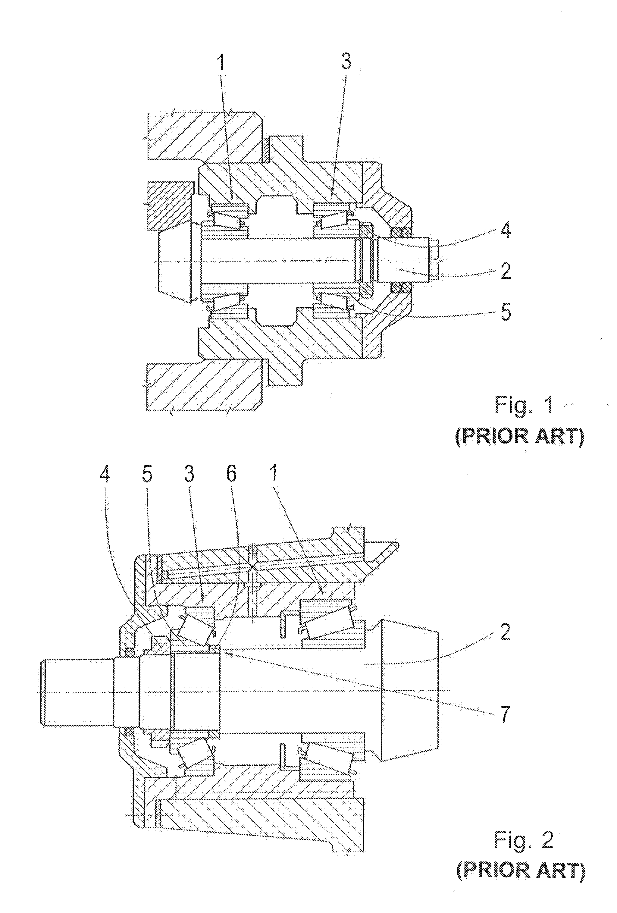
The disadvantage of such a method for adjusting the bearing play lies in the poor reproducibility of the exact bearing play adjustment, since the position of the inner race 5 of the bearing is not predetermined and depends on the fitting of the locking nut 4.
This makes the process time-consuming and therefore more costly.

Method used


Image

  • Shaft-bearing subassembly for a wind turbine transmission
  • Shaft-bearing subassembly for a wind turbine transmission
  • Shaft-bearing subassembly for a wind turbine transmission

Examples


Embodiment Construction

[0036]In the description various embodiments serve to demonstrate the invention. For that reason reference is made to various drawings. It must be made clear that the drawings are not intended to have any restrictive force; the invention is limited only by the claims. Thus, the drawings serve illustrative purposes; for the sake of clarity, the form of some elements in the drawings may be exaggerated.

[0037]The term “comprises / comprise” does not mean that besides the element said to be comprised, no other elements, in particular including further elements of the same type, may not also be comprised.

[0038]The term “connected / attached” in the claims and the description is not to be understood as a restriction to direct connections unless otherwise indicated. Consequently the expression “part A is connected to part B” is not restricted to direct contact of parts A and B, but also includes indirect contact between part A and part B; in other words it also includes the case in which interm...


PUM


Abstract

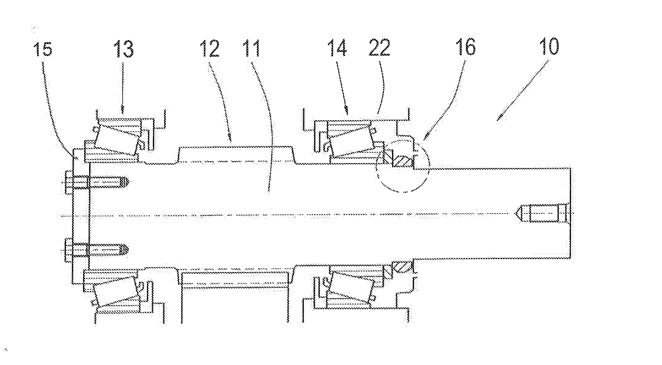
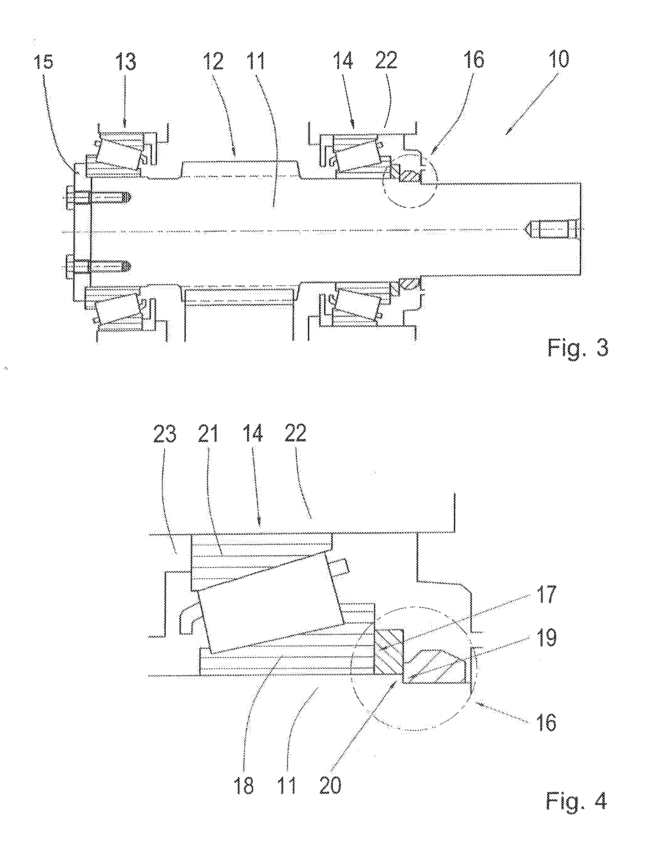
A shaft-bearing subassembly (10) which includes at least one shaft (11) mounted by way of at least first and second roller bearings (13, 14). The first and second roller bearings (13, 14) are mounted on the at least one shaft (11) with an intermediate space between them. The first roller bearing (13) is fixed axially and the second roller bearing (14) is secured by way of a retaining element (16). The retaining element (16) is on the side of the second roller bearing (14) farthest away from the first roller bearing (13), and has a first contact surface (17) which limits the movement of an inner race (18) of the second roller bearing (14) in at least one direction, and a second contact surface (19) which is in contact with an abutment (20) on the shaft (11).

Description

[0001]This application is a National Stage completion of PCT / EP2014 / 074824 filed Nov. 18, 2014, which claims priority from German patent application serial no. 10 2013 226 519.0 filed Dec. 18, 2013.FIELD OF THE INVENTION[0002]The present invention concerns a shaft-bearing subassembly for a wind turbine transmission and a method for fitting roller bearings onto a shaft of a wind turbine transmission.BACKGROUND OF THE INVENTION[0003]In transmissions, shafts are mounted by means of bearings so that the shafts can rotate. To be able to fix the position of the shaft in the transmission as accurately as possible, among other things movement of the bearings axially on the shaft must be prevented. Another important requirement is that the bearing play can be adjusted accurately.[0004]At present a number of methods are known for assembling a bearing pair, for example a pair of roller bearings, on a shaft, for example from “Roller bearings in industrial transmissions” by SKF. FIG. 1 illustrat...

Claims


Application Information

Patent Timeline
IPC IPC(8): F16H57/021F16C19/54F16H57/023F03D80/70F03D15/00
CPCF16H57/021F03D80/70F03D15/00F16H57/023F16C19/548F16H2057/0227F05B2240/60F05B2240/54F16H2057/0216F16H2057/0221F05B2230/60F16C25/06F16H57/022F05B2240/50F05B2260/4031F16C19/364F16C2361/61F16C2360/31Y02E10/72Y02P70/50F16C2229/00
Inventor VERDYCK, BERT
Owner ZF FRIEDRICHSHAFEN AG
Why Eureka
Try Eureka