
Method of wastewater treatment with excess sludge withdrawal reduced

一种排水处理、剩余污泥的技术,应用在水/污泥/污水处理、生物水/污水处理、水/污水多级处理等方向,能够解决膜过滤装置大、透射流束小、大活性污泥槽等问题

Active Publication Date: 2007-06-20
KURARAY CO LTD
View PDF2 Cites 2 Cited by
  • Summary
  • Abstract
  • Description
  • Claims
  • Application Information

AI Technical Summary

Problems solved by technology

In addition, by not pumping out the sludge and forming a fully oxidized state in which the growth rate of the sludge is balanced with the rate of oxidation of the sludge itself, a system that does not generate excess sludge can be constructed theoretically. If the state of full oxidation is formed in the mud tank, the MLSS in the aeration tank is very high, so there is a disadvantage that a very large activated sludge tank must be installed
In addition, in this case, there is also a problem that the sludge is finely divided, and the sludge cannot be separated by natural sedimentation.
Generally, in order to temporarily treat the sludge in the settling tank, the operation of adding a flocculant to settle the sludge is performed. However, if the flocculant is added to the aeration tank, the sludge will settle, and the aeration in the aeration tank will cause the sludge to settle. Gas is not sufficiently carried out, and a large amount of sludge settled in the settling tank is discharged out of the system as excess sludge, thus, no coagulant is used in the full oxidation tank for reducing excess sludge capacity
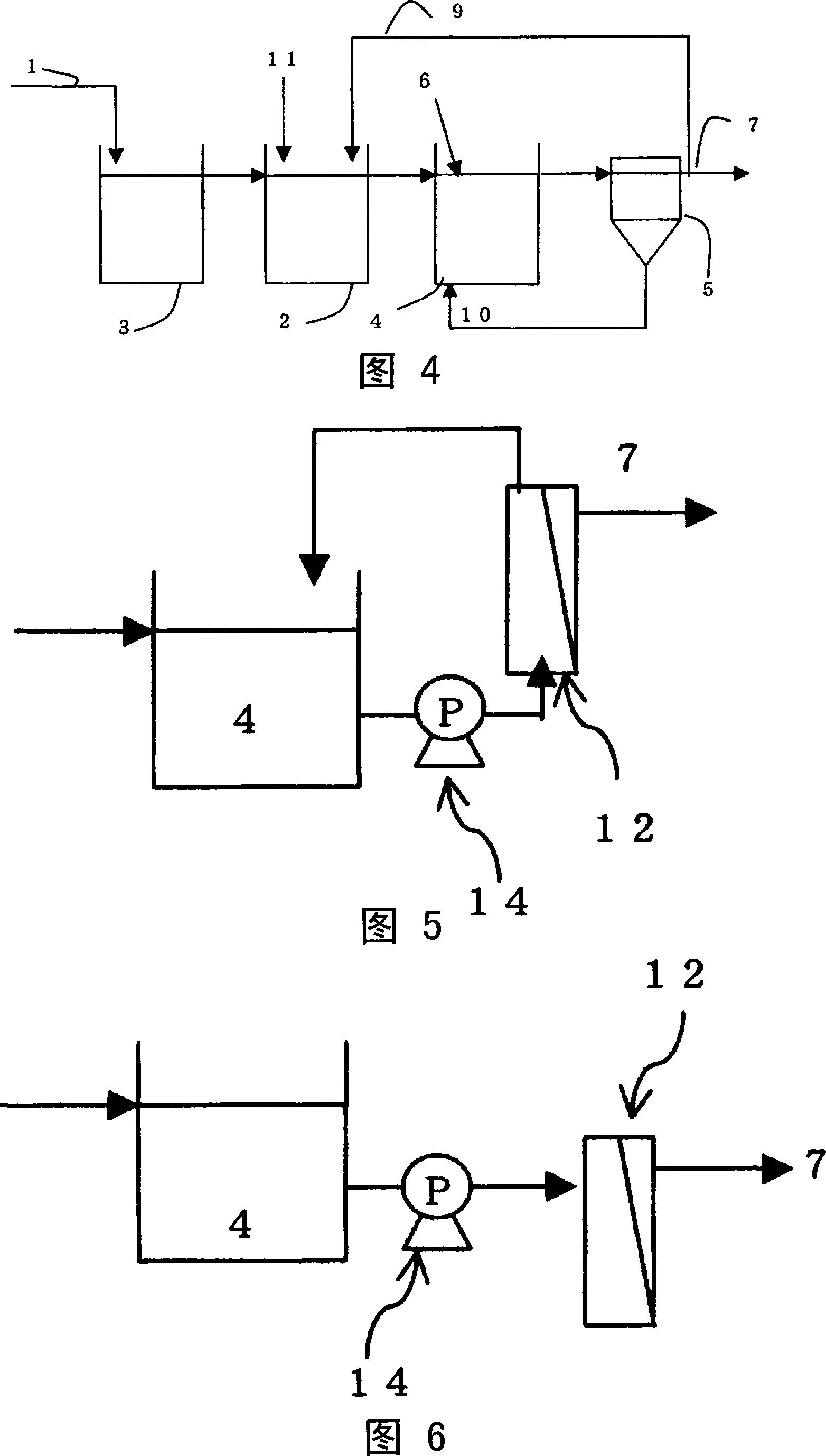
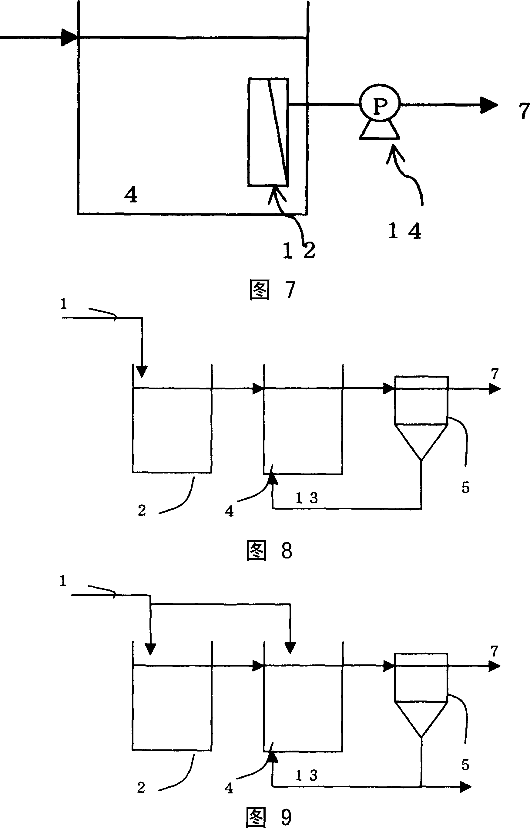
[0007] Although the present inventors have proposed a treatment device and a drainage treatment method that do not generate excess sludge by combining an aeration tank and a total oxidation tank using a microbial immobilization carrier with a separation membrane, but, due to the suitable separation membrane The pore size is less than 0.1 micron, so there is a problem that the transmitted flux is very small, the membrane filtration device is large, and the equipment cost and operating cost are very large (see Patent Document 2)
Also, no mention of nitrogen removal

Method used


Image

  • Method of wastewater treatment with excess sludge withdrawal reduced
  • Method of wastewater treatment with excess sludge withdrawal reduced
  • Method of wastewater treatment with excess sludge withdrawal reduced

Examples


Embodiment 1

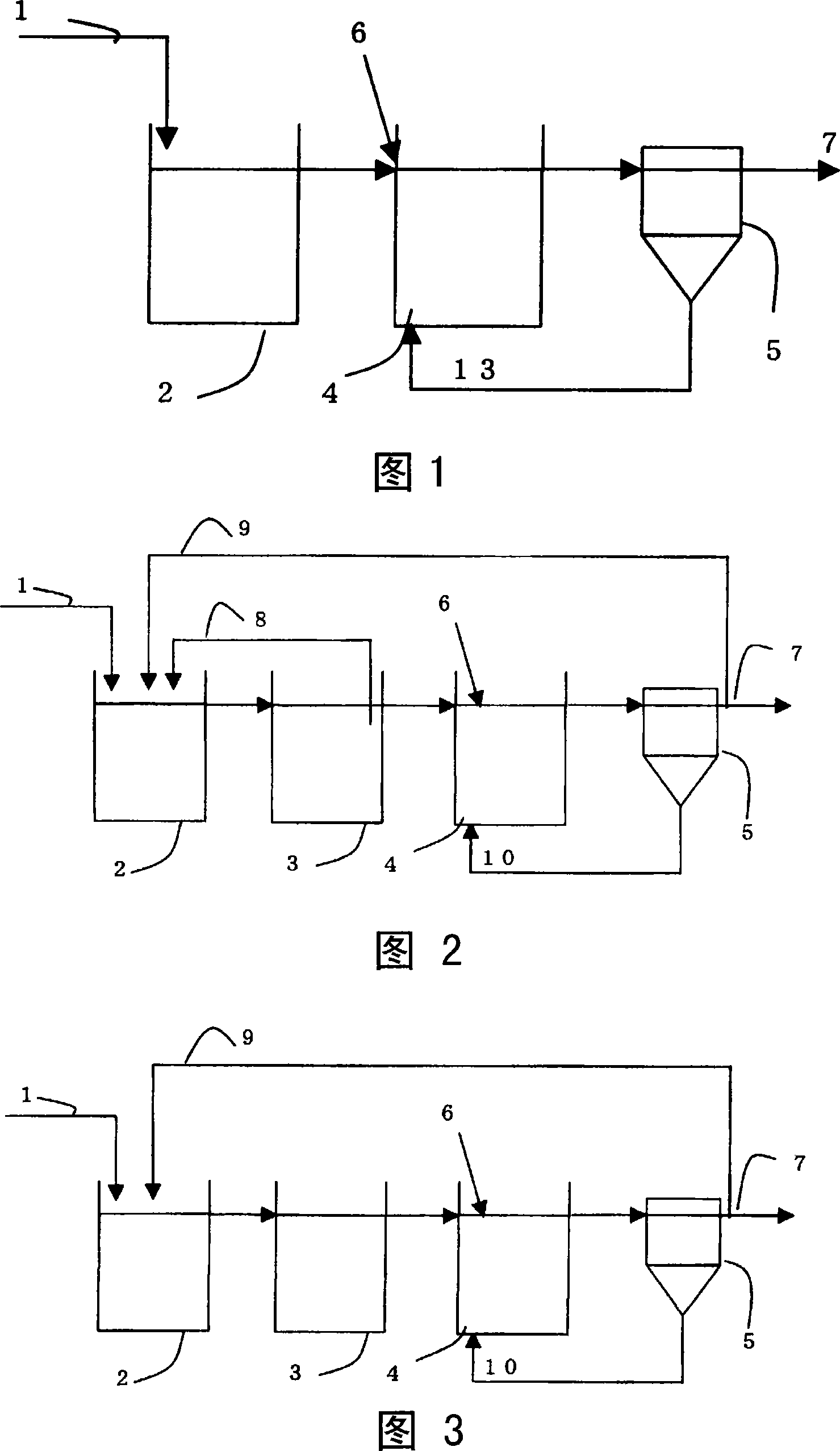
[0058] According to the process shown in Figure 1, the capacity is 320m 3 The carrier flow aeration tank with a capacity of 240m 3 of full oxidation tanks and a capacity of 50m 3Drainage treatment device formed by sedimentation tank, carried out 400m 3 / day of chemical drainage treatment. In the carrier flow aeration tank, put 32m 3 Acetal polyvinyl alcohol-based colloid carrier (about 4mm in diameter). In addition, 10 mg / L of polyaluminum chloride (inorganic flocculant) was added to the wastewater treated in the carrier flow tank. According to the present invention, the BOD volume load of the aeration tank according to the carrier flow is 2.5kg / m 3 When operating in the daily mode, the MLSS of the total oxidation tank increases slowly, but when the BOD sludge load is 0.05kg-BOD / kg-MLSS per day, the MLSS of the total oxidation tank is about 10000mg / L, which is basically constant.

[0059] The coagulant was continuously supplied for about one month from the start of the o...

Embodiment 2

[0067] According to the process shown in Figure 2, the capacity is 30m 3 denitrification tank with a capacity of 30m 3 Nitrification tank with a capacity of 25m 3 of full oxidation tanks and a capacity of 25m 3 The drainage treatment device formed by the settling tank, the ammoniacal nitrogen is 50mg / L, the BOD is 200mg / L, and the drainage is 200m 3 / day of chemical drainage treatment. In the denitrification tank and nitrification tank, put 3.3m 3 Acetal polyvinyl alcohol-based colloid carrier (about 4mm in diameter), according to 600m 3 / day level, return the drainage from the nitrification tank to the denitrification tank. In addition, 10 mg / L of polyaluminum chloride (inorganic flocculant) was added to the wastewater treated by the nitrification tank. In addition, according to 600m 3 / day level, return the drainage from the outlet of the sedimentation tank to the denitrification tank. According to the present invention, according to the nitrogen volume load of den...

Embodiment 3

[0069] According to the process shown in Figure 3, the capacity is 270m 3 denitrification tank with a capacity of 270m 3 Nitrification tank with a capacity of 100m 3 of full oxidation tanks and a capacity of 250m 3 The drainage treatment device formed by the settling tank, the ammoniacal nitrogen is 40mg / L, the BOD is 160mg / L, and the drainage is 2000m 3 / day of chemical drainage treatment. In the denitrification tank and nitrification tank, put 27m 3 Acetal polyvinyl alcohol-based colloid carrier (about 4mm in diameter). In addition, 10 mg / L of aluminum sulfate (inorganic flocculant) was added to the wastewater treated by the nitrification tank. In addition, according to 6000m 3 / day level, return the drainage from the outlet of the sedimentation tank to the denitrification tank. According to the present invention, according to the nitrogen volume load of denitrification tank and nitrification tank is 0.3kg / m 3 When operating in the daily mode, the MLSS of the full o...


PUM

PropertyMeasurementUnit
pore sizeaaaaaaaaaa
pore sizeaaaaaaaaaa
pore sizeaaaaaaaaaa

Abstract

A method of wastewater treatment that reduces equipment cost and running cost and realizes high-efficiency implementation and further tank miniaturization, and that reduces excess sludge withdrawal. There is provided a method of wastewater treatment with excess sludge withdrawal reduced, characterized in that there are installed an aeration tank wherein wastewater is brought into contact with carrier particles under aerobic conditions, a complete oxidation tank and a sedimentation tank, and that operation is made while maintaining the BOD sludge load in the complete oxidation tank at = 0.08 kg-BOD / kg-MLSS day, and that a coagulant is charged in the complete oxidation tank in order to improve the settling in the sedimentation tank.

Description

technical field [0001] The present invention relates to a wastewater treatment method with a small extraction amount of excess sludge. Background technique [0002] In the past, in the drainage treatment method using the activated sludge method, in the aeration tank, the drainage was brought into contact with the activated sludge under aerobic conditions, the sludge was allowed to settle in the sedimentation tank, and a part was returned to the aeration tank , the other part is extracted as excess sludge, thus, the BOD volume load is 0.3-0.8kg / m 3 · Under daily conditions, normal operation can be performed (for example, refer to Non-Patent Document 1). On the other hand, people are developing a carrier that can hold microorganisms at a high concentration. If this carrier is used, 2 to 5 kg / m can be applied 3 · The higher BOD volume load per day can reduce the overall size of the aeration tank (for example, refer to Non-Patent Document 2). [0003] In the past activated sl...

Claims


Application Information

Patent Timeline
Patent Type & Authority Applications(China)
IPC IPC(8): C02F3/12C02F1/52C02F3/06C02F3/08
CPCC02F3/1226C02F9/00C02F2101/38Y10S210/908C02F1/52C02F1/44C02F3/12Y02W10/10
Inventor 马场泰弘藤井弘明冈部日出彦小林悟朗
Owner KURARAY CO LTD
Learn More