Capsulation structure of white LED
A technology of LED encapsulation and white light, which is applied in electrical components, electric solid-state devices, circuits, etc., can solve problems such as uneven distribution of light-emitting phosphors, uneven light color and brightness of light-emitting diodes, and low light quality, and achieve simplified packaging structure, reduce the uneven distribution problem, and solve the effect of uniformity problem
- Summary
- Abstract
- Description
- Claims
- Application Information
AI Technical Summary
Problems solved by technology
Method used
Image
Examples
Embodiment 1
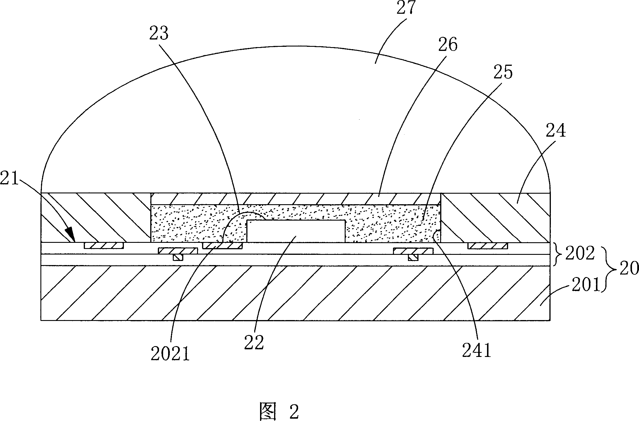
[0051] Referring to FIG. 2 , it shows a cross-sectional view of an embodiment of a white LED packaging structure according to the present invention.
[0052] In this embodiment, the package structure of the white light LED includes a base 20 , a chip 22 , a bonding wire 23 , a covering layer 24 , a resin 25 , a uniform fluorescent film 26 and an optical lens 27 .
[0053]As shown in the figure, the base 20 includes a substrate 201 and a printed circuit layer 202. A printed circuit layer 202 with electrode pads 2021 is disposed on the substrate 201, and a chip 22 is disposed on the surface 21 of the printed circuit layer 202. On the surface 21 of the printed circuit layer 202, a coating 24 with a penetration hole 241 is additionally arranged, so that the chip 22 is located in the penetration hole 241 of the coating 24, and the bonding wire 23 is set on the chip 22, and the welding The other end of the wire 23 is connected to the electrode pad 2021 of the printed circuit layer 2...
Embodiment 2
[0057] This embodiment is slightly different from the embodiment in FIG. 2 , and only the differences will be described here, and the similarities will not be repeated here.
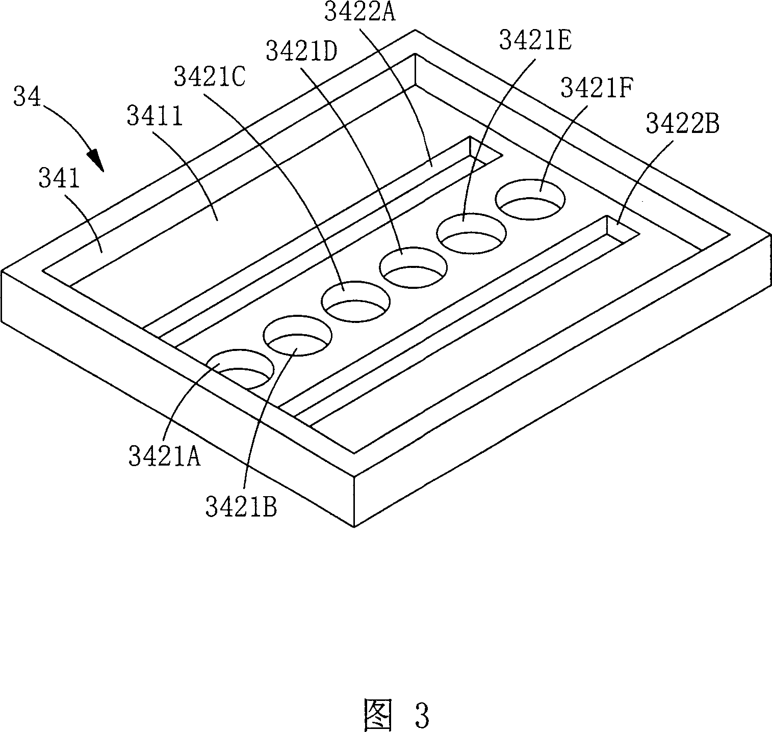
[0058] Referring to Fig. 3, in the coating 34 of this embodiment, it has a groove 341, and the groove 341 has a flat bottom 3411, and a plurality of through holes 3421A3421B3421C3421D3421E3421F are set on the bottom 3411, and the plurality of through holes 3421A3421B3421C3421D3421E3421F The center of the bottom 3411 of the groove 341 is aligned in a straight line, and a strip-shaped through hole 3422A3422B is disposed on both sides of the through hole 3421A3421B3421C3421D3421E3421F.
[0059] As mentioned above, the penetration holes 3422A, 3422B are arranged corresponding to the electrode pads 3021A, 3021B on the surface 31 of the printed circuit layer 302. When the coating layer 34 is disposed on the surface 31 of the printed circuit layer 302, the electrode pads 3021A, 3021B can be respectively exposed....
Embodiment 3
[0065] Referring to FIG. 5 and FIG. 6, it shows another embodiment according to the present invention.
[0066] In FIG. 5 , it shows a cladding structure used in an embodiment of the present invention, and FIG. 6 is a cross-sectional view of an embodiment having the cladding structure of FIG. 5 .
[0067] This embodiment is slightly different from the embodiment in FIG. 2 , and only the differences will be described here, and the similarities will not be repeated here.
[0068] As shown in FIG. 5 , this structure is provided with a first groove 541 with a predetermined depth on the surface of the coating 54 , and a bottom 5411 of the first groove 541 is provided with a groove that is smaller than the first groove 541 and has a predetermined depth. In the second groove 542, four through holes 5431A5431B5431C5431D are arranged in a straight line at the center of the bottom 5421 of the second groove 542, and a rectangular through hole 5432A5432B is arranged on both sides of the s...
PUM
 Abstract
Description
Claims
Application Information
 - R&D
- Intellectual Property
- Life Sciences
- Materials
- Tech Scout
- Unparalleled Data Quality
- Higher Quality Content
- 60% Fewer Hallucinations
Browse by: Latest US Patents, China's latest patents, Technical Efficacy Thesaurus, Application Domain, Technology Topic, Popular Technical Reports.
© 2025 PatSnap. All rights reserved.Legal|Privacy policy|Modern Slavery Act Transparency Statement|Sitemap|About US| Contact US: help@patsnap.com


