Radiator

A technology of radiator and heat dissipation fin, applied in the direction of instruments, electric solid-state devices, semiconductor devices, etc., can solve the problems of inconvenience and trouble in production, and achieve the effect of stable fastening

Inactive Publication Date: 2007-05-09
FU ZHUN PRECISION IND SHENZHEN +1
View PDF1 Cites 1 Cited by
  • Summary
  • Abstract
  • Description
  • Claims
  • Application Information

AI Technical Summary

Problems solved by technology

Once the top or bottom of the fastening structure of the heat dissipation fins is combined with other components, the heat conduction medium such as heat conduction solder paste will directly penetrate into the heat dissipation body along the gap between adjacent heat dissipation fins during the welding and fixing process to form tin Beads bring inconvenience and trouble to production

Method used


Image

  • Radiator
  • Radiator
  • Radiator

Examples


Embodiment Construction

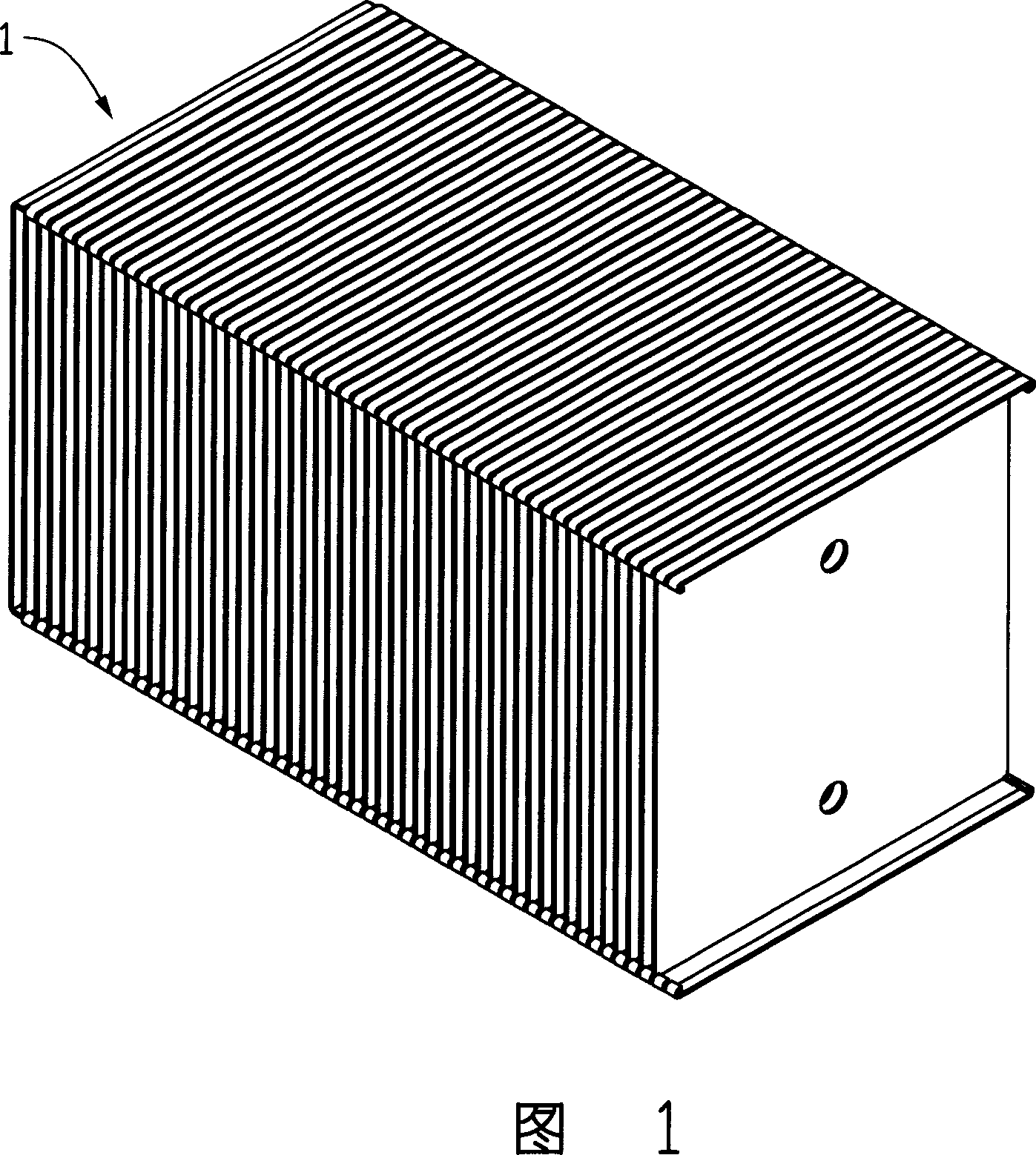
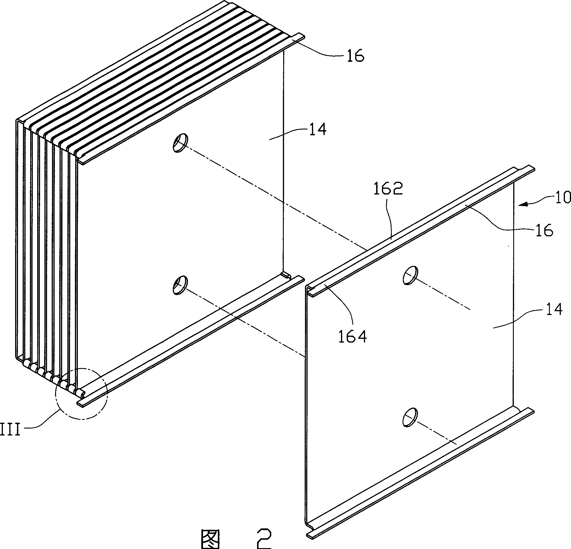
[0013] Please refer to Fig. 1 to Fig. 3, in the first embodiment of the present invention, the radiator 1 includes a plurality of heat dissipation fins 10 stacked on top of each other, the radiator 1 can be directly attached to the surface of the heating element (not shown), It can be pasted on a heat conduction plate (not shown in the figure), and then contact the heating element through the heat conduction plate.

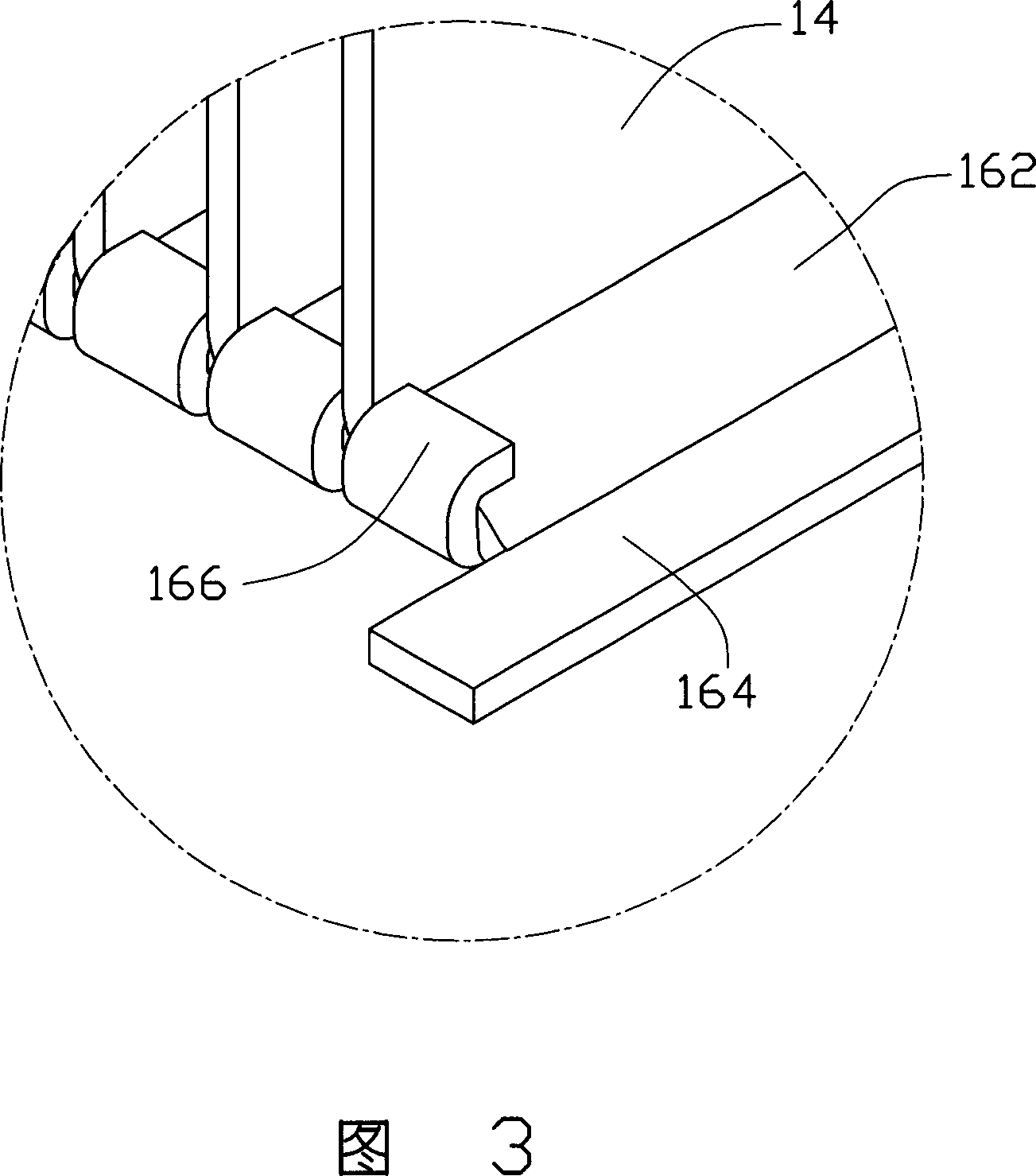
[0014] As shown in FIGS. 2 to 4 , each heat dissipation fin 10 has a flat heat dissipation body 14 , and the upper and lower edges of the body 14 are respectively bent and extended in the same direction with a folded edge 16 . Each flange 16 includes a receiving portion 162 extending along the edge of the main body 14 , a connecting portion 163 extending along the end of the receiving portion 162 , and a fastening portion extending from the free end of the connecting portion 163 parallel to the receiving portion 162 164. The connecting portion 163 is inclined to ...


PUM


Abstract

The radiator includes heat elimination fins superposed each other. Each fin possesses a main body. One end of the main body is bent and extended to form an edge fold. Each edge fold includes a clip. An edge fold includes an accepting part and an extended clip connection part. The clip connection part of next fin is superposed to the accepting part of previous fin. The clip of the next fin is clipped and fixed on the accepting part of the previous fin so as to form an isolated area. In procedure for welding radiator, heat-conducting medium is blocked off inside the isolated area so as to prevent heat-conducting medium from passing through gap between adjacent heat elimination fins to infiltrate to space between main bodies. Features are: stable buttoned heat elimination fins.

Description

【Technical field】 [0001] The invention relates to a radiator, in particular to a radiator used on electronic components. 【Background technique】 [0002] With the rapid development of the computer industry, the processing capabilities of electronic components such as central processing units have been continuously upgraded, and the radiators have also tended to be diversified. The radiators used in this process are also being continuously improved, such as the initial aluminum extrusion or groove-shaped integrated radiators, and later the radiators formed by welding or inserting most single-piece cooling fins with the base, and A heat sink formed by continuous bending of a metal sheet and combined with a base, etc. [0003] As disclosed in Chinese Patent Publication No. 2713637Y, a traditional combination structure of heat dissipation fins is composed of a plurality of heat dissipation fins interlocked together. Each heat dissipation fin has a heat dissipation body, the two...

Claims


Application Information

Patent Timeline
Patent Type & Authority Applications(China)
IPC IPC(8): H01L23/367G06F1/20H05K7/20
Inventor 陈俊吉翁世勋余光周大远刘金标
Owner FU ZHUN PRECISION IND SHENZHEN
Why Eureka
Try Eureka