Dielectric barrier discharge excimer light source
A dielectric barrier and excimer technology, applied in discharge lamps, circuits, lasers, etc., can solve problems such as voltage increase and achieve the effect of improving luminous efficiency
- Summary
- Abstract
- Description
- Claims
- Application Information
AI Technical Summary
Problems solved by technology
Method used
Image

Examples
no. 1 example
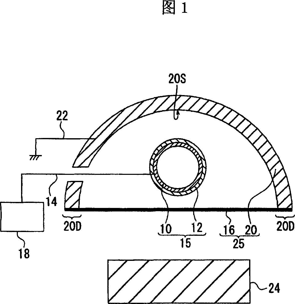
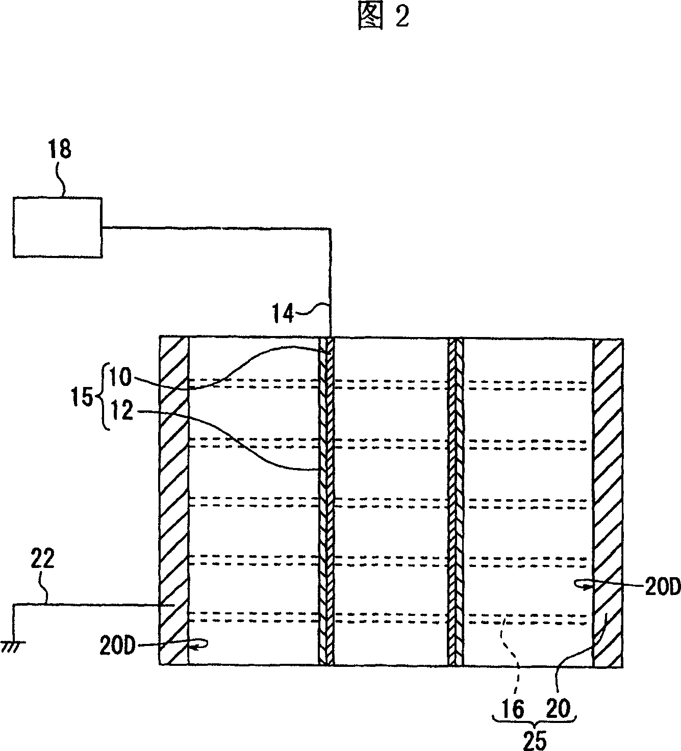
[0101] The structure and working principle of the first dielectric barrier discharge excimer light source of the present invention will be described with reference to FIG. 1 and FIG. 2 . Fig. 1 is a schematic cross-sectional view obtained by cutting along the longitudinal direction perpendicular to the anode of the first dielectric barrier discharge excimer light source. Fig. 2 is a schematic longitudinal sectional view obtained by cutting along the longitudinal direction parallel to the anode of the first dielectric barrier discharge excimer light source.
[0102] The anode electrode 10 consists of a straight and long cylinder covered with a dielectric 12 at the periphery of the cylinder. The anode 15 has an anode electrode 10 and a dielectric 12 . In the following description, a structure composed of an anode electrode and a dielectric is also referred to as an anode structure.
[0103] The cathode 25 has a straight semi-cylindrical cathode portion 20 and a cathode wire gr...
no. 2 example
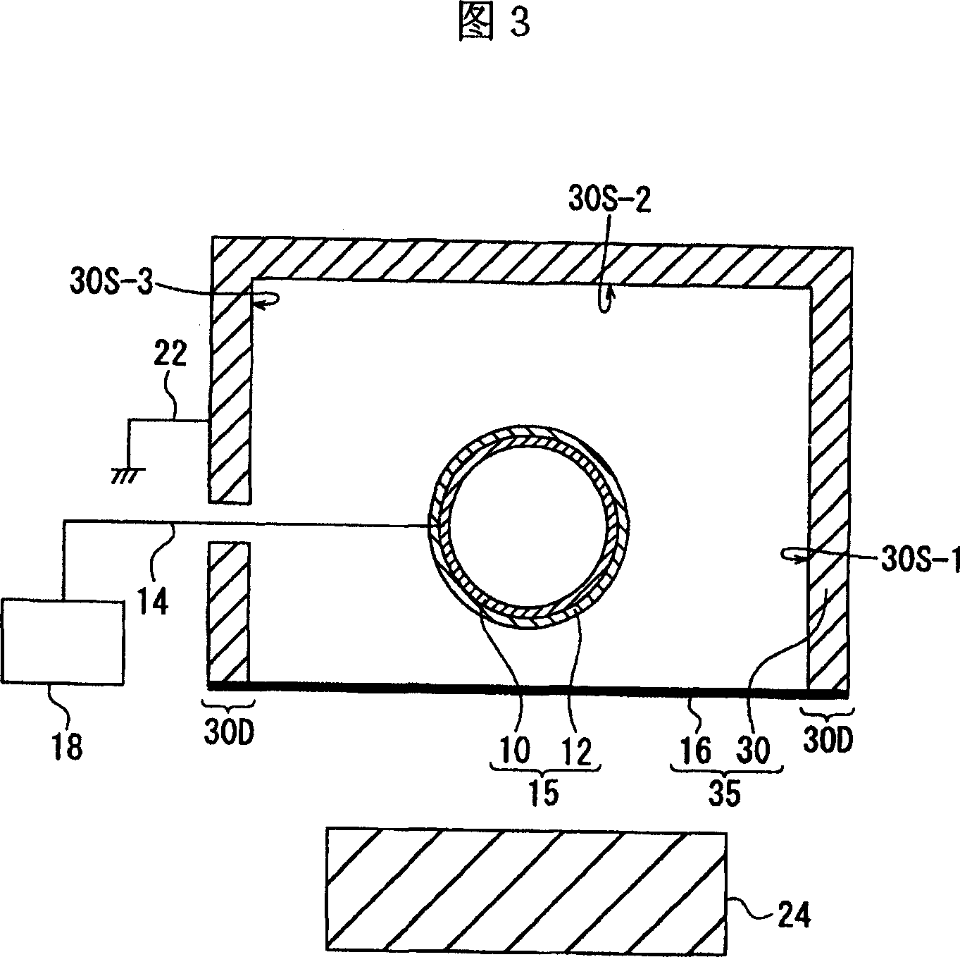
[0117] The structure of the second dielectric barrier discharge excimer light source of the present invention will be described with reference to FIG. 3 . Fig. 3 is a schematic cross-sectional view obtained by cutting along the longitudinal direction perpendicular to the anode of the second dielectric barrier discharge excimer light source. A schematic longitudinal sectional view taken along a longitudinal direction parallel to the anode is omitted since it is the same as that in FIG. 2 . In the following description, in principle, only the cross-sectional view of the light source is shown, and the vertical cross-sectional view that is the same as that in FIG. 2 is omitted unless otherwise necessary.
[0118] The second dielectric barrier discharge excimer light source has the same characteristics as the above-mentioned first dielectric barrier discharge excimer light source, that is, there is an anode electrode 10 made of a hollow straight long cylinder covered with a dielect...
no. 3 example
[0121] The structure of the third dielectric barrier discharge excimer light source of the present invention will be described with reference to FIG. 4 . Fig. 4 is a schematic cross-sectional view of a third dielectric barrier discharge excimer light source cut along a longitudinal direction perpendicular to the anode. A schematic longitudinal sectional view taken along a longitudinal direction parallel to the anode is omitted since it is the same as that in FIG. 2 .
[0122] The third dielectric barrier discharge excimer light source has the same characteristics as the above-mentioned first dielectric barrier discharge excimer light source, that is, it has an anode electrode 40 made of a straight long cylinder covered with a dielectric, and contains the anode electrode 40 The elongated cathode portion 30. However, the shape of the anode electrode 40 is different from that of the cathode portion 30 . The anode electrode 40 is covered with a dielectric 42 and is a straight pi...
PUM
 Abstract
Description
Claims
Application Information
 - R&D
- Intellectual Property
- Life Sciences
- Materials
- Tech Scout
- Unparalleled Data Quality
- Higher Quality Content
- 60% Fewer Hallucinations
Browse by: Latest US Patents, China's latest patents, Technical Efficacy Thesaurus, Application Domain, Technology Topic, Popular Technical Reports.
© 2025 PatSnap. All rights reserved.Legal|Privacy policy|Modern Slavery Act Transparency Statement|Sitemap|About US| Contact US: help@patsnap.com