
Laminated capacitor and manufacturing method thereof

A technology of a multilayer capacitor and a manufacturing method, which can be applied in the directions of multilayer capacitors, multiple fixed capacitors, fixed capacitor terminals, etc., can solve problems such as hindering large capacitance and hindering thinning of products, and achieve cost reduction, ESL reduction, Short-circuit failure reduction effect

Active Publication Date: 2007-03-28
TDK CORP
View PDF1 Cites 11 Cited by
  • Summary
  • Abstract
  • Description
  • Claims
  • Application Information

AI Technical Summary

Problems solved by technology

In this way, the thickening of the ceramic layer means that while hindering the thinning of the product, it also hinders the increase in capacitance.

Method used


Image

  • Laminated capacitor and manufacturing method thereof
  • Laminated capacitor and manufacturing method thereof
  • Laminated capacitor and manufacturing method thereof

Examples


Embodiment Construction

[0056] 1. Laminated capacitors

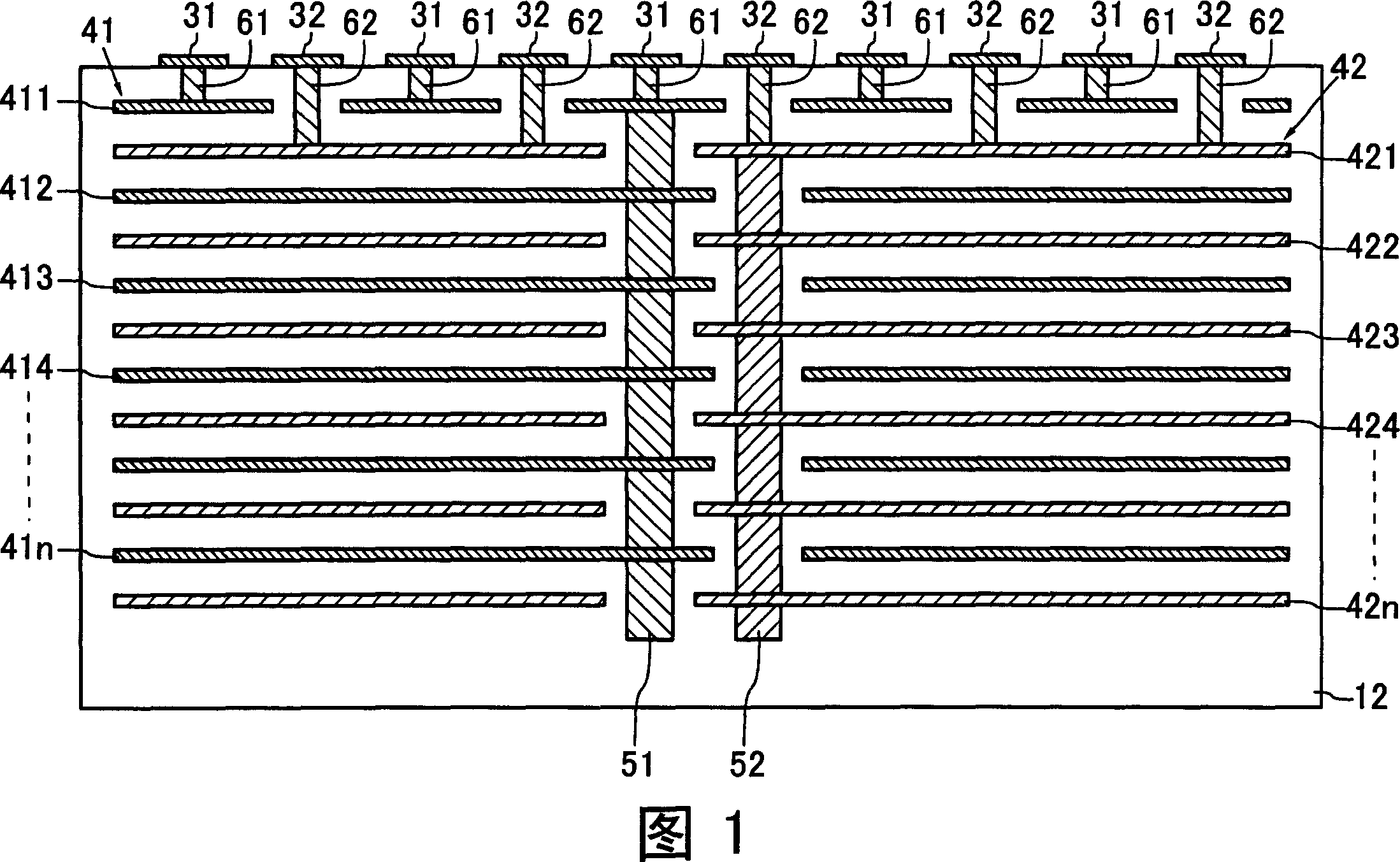
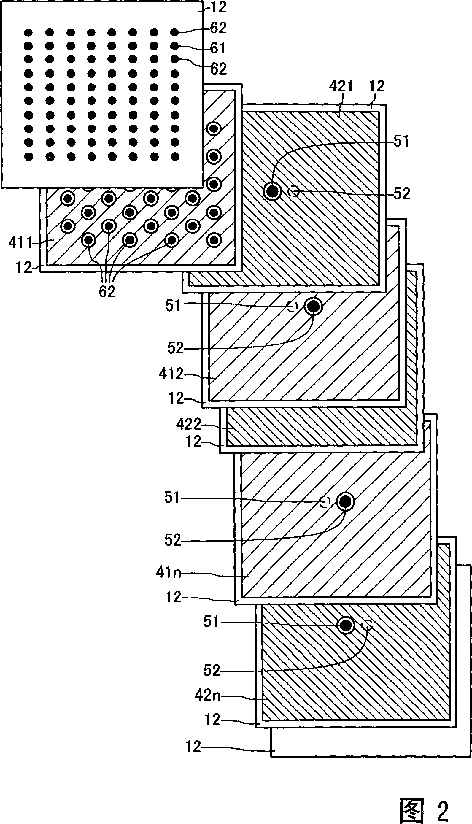
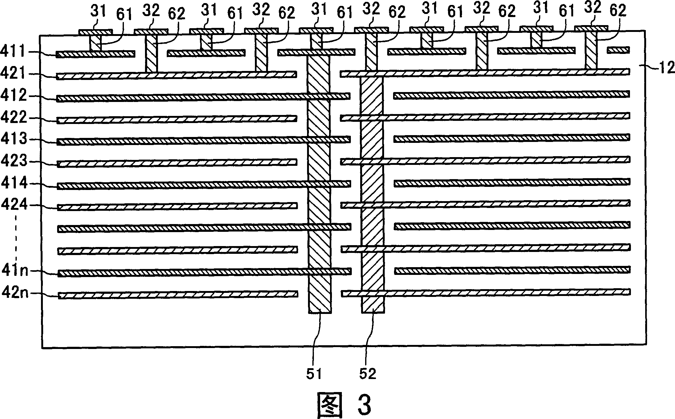
[0057] The multilayer capacitor shown in FIGS. 1 and 2 includes a dielectric substrate 12, first and second terminal electrodes 31 and 32, first and second inner electrode groups 41 and 42, and first and second outer layer via conductors 61. , 62, and the first and second inner layer via conductors 51,52. The dielectric matrix 12 is, for example, a ceramic dielectric. Dimensions of the dielectric substrate 12 are, for example, about 10 mm×10 mm×0.85 mm in length×width×thickness. The first and second terminal electrodes 31 and 32 are dispersedly arranged on the surface of the dielectric substrate 12 with intervals therebetween. In FIG. 2 , terminal electrodes are omitted.

[0058] The first internal electrode group 41 includes first internal electrodes 411 to 41 n and is embedded in the dielectric substrate 12 . Each of the first internal electrodes 411 to 41n is provided in layers. The second internal electrode group 42 includes second int...


PUM


Abstract

A laminated capacitor capable of reducing ESL, includes: first terminal electrodes and second terminal electrodes arranged at intervals on one surfaces of the dielectric body; first outer through-hole conductors each connecting each first terminal electrode to one first internal electrode; second outer through-hole conductors each connecting each second terminal electrode to one second internal electrode; a first inner through-hole conductor connecting the first internal electrodes to one another; and a second inner through-hole conductor connecting the second internal electrodes to one another.

Description

technical field [0001] The present invention relates to stacked capacitors and methods of manufacturing the same. More specifically, it relates to a multilayer capacitor having a small equivalent series inductance (hereinafter referred to as ESL) and a method of manufacturing the same. Background technique [0002] In a CPU or the like, if the power supply voltage changes, its operation is greatly affected. Therefore, multilayer capacitors are arranged around the CPU as a means of suppressing changes in the power supply voltage and stabilizing the power supply. [0003] However, in recent years, as the operating frequency of the CPU has increased, high-speed and large current changes are likely to occur, and the influence of the ESL of the multilayer capacitor itself has become greater. There is concern that the total inductance including this ESL will affect the voltage change of the power supply. make an impact. [0004] As a technique for reducing ESL, for example, JP-A...

Claims


Application Information

Patent Timeline
Patent Type & Authority Applications(China)
IPC IPC(8): H01G4/30H01G4/38
CPCH01G4/232H01G4/30
Inventor 富樫正明安彦泰介
Owner TDK CORP
Learn More