
Pipe support capable of load-bearing minisize active particle source

A technology of radioactive particles and pipeline support, which is applied in the field of pipeline support, can solve the problems of inability to adjust the treatment plan, complicated operation, and inability to take it out, and achieve the effect of being beneficial to treatment and rehabilitation, convenient to use, and simple in structure

Inactive Publication Date: 2007-03-14
SECOND MILITARY MEDICAL UNIV OF THE PEOPLES LIBERATION ARMY
View PDF0 Cites 16 Cited by
  • Summary
  • Abstract
  • Description
  • Claims
  • Application Information

AI Technical Summary

Problems solved by technology

However, radioactive particles are often implanted through surgery, or puncture implantation under the guidance of B-ultrasound or CT, which has disadvantages such as complicated operation, large trauma, and unfavorable recovery of patients, and cannot be removed after implantation, and the treatment plan cannot be adjusted in time according to the curative effect

Method used


Image

  • Pipe support capable of load-bearing minisize active particle source
  • Pipe support capable of load-bearing minisize active particle source

Examples


Embodiment 1

[0015] Example 1. A pancreatic duct stent capable of carrying miniature sources of radioactive particles

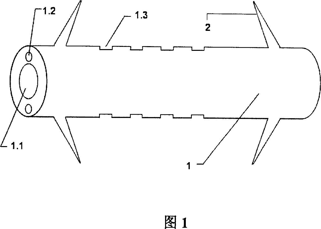
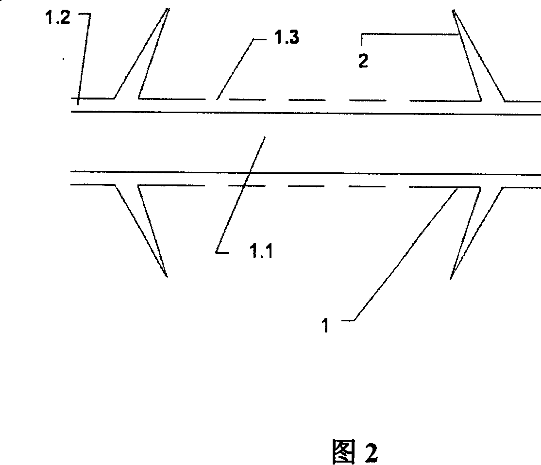
[0016] The length of the drainage tube of the present invention is 54.4mm, the outer diameter is 3.2mm, the diameter of the drainage cavity is 1.8mm, and one particle channel is arranged in the tube wall. The inner diameter of the particle channel is 0.8mm. There are three irradiation windows on the outer wall of the particle channel, the length, width and height are 4.4×0.7×0.2 (mm), and the center interval of adjacent irradiation windows is 10.0mm. The radiation windows on both sides are 15.0mm away from both ends of the drainage tube. The length of the two barbs is both 7mm, and the root is 5mm from both ends of the drainage tube. The miniature radioactive particle source has a length of 4.5mm and a diameter of 0.8mm. Single particle activity 0.5mCi. This designed therapeutic dose is 50Gy loaded radioactivity 125 The pancreatic duct stent of I particle source has ...

Embodiment 2

[0017] Example 2. A bile duct stent capable of carrying miniature sources of radioactive particles

[0018] The length of the drainage tube of the present invention is 69.4 mm, the outer diameter is 3.6 mm, the diameter of the drainage cavity is 1.5 mm, and two symmetrical particle channels are arranged in the tube wall. The inner diameter of the particle channel is 0.8mm. There are 6 irradiation windows on the outer wall of each particle channel, the length, width and height are 4.4×0.7×0.2 (mm), and the center interval of adjacent irradiation windows is 5.0mm. The distance between the irradiation window at the head end and the starting end of the drainage tube was 25.0 mm, and the distance between the irradiation window at the tail end and the end of the drainage tube was 15.0 mm. The length of the two barbs is 7mm, and the root is 5mm from both ends of the bracket. The miniature radioactive particle source has a length of 4.5mm and a diameter of 0.8mm. The single particl...


PUM


Abstract

The invention relates to the field of the medical apparatus and instruments, it is a pipeline bracket which can bearing micro radiation particle resource, and it mainly used in the treatment of pancreatic cancer or bile duct cancer in the metaphase or late stage. It also has the function of conduction consisting of the drainage tube 1 and the face to face bards 2 mounted on the two ends of the drainage tube. The inner cavity of the drainage tube is the drainage cavity 1.1, the particle duct 1.2 that its diameter matching with the outer diameter of the micro radiation particle resource is mounted in the tube wall. The irradiation window 1.3 of the micro radiation particle resource is equipped in the outer wall. The length and width of the irradiation window are on the small side of the micro radiation particle resource. The invention is simple in structure, and can be posted in vivo by endoscope via tiny wound, convenient to use and has the function of actinotherapy and conduction.

Description

technical field [0001] The invention relates to the technical field of medical devices, and is a pipeline support capable of carrying micro-radioactive particle sources, which is mainly used for internal irradiation treatment of middle and advanced pancreatic cancer or cholangiocarcinoma and has a drainage function. Background technique [0002] Pancreatic cancer and cholangiocarcinoma are a group of malignant tumors of the digestive tract with dangerous conditions, low cure rate, and extremely poor prognosis. Most of them are in the middle and late stages when they are discovered, and they are often unresectable. Tumors often compress the pancreatic and bile ducts, causing strictures or obstructions. For pipeline stenosis or obstruction, at present, endoscopic placement of a pipeline stent with drainage function is mainly used to relieve clinical symptoms. The commonly used clinical pipe support consists of a drainage tube and opposite barbs arranged ...

Claims


Application Information

Patent Timeline
Patent Type & Authority Applications(China)
IPC IPC(8): A61M36/00A61M36/04A61M39/00A61F2/82A61K51/02A61F2/04
CPCA61M27/008A61F2/04A61F2210/0095A61N5/1002A61N5/1027A61F2002/041A61N2005/1018
Inventor 李兆申刘岩路筝
Owner SECOND MILITARY MEDICAL UNIV OF THE PEOPLES LIBERATION ARMY
Learn More