Eureka AIR delivers breakthrough ideas for toughest innovation challenges, trusted by R&D personnel around the world.

System apparatus, device and method for correcting microphone

A technology for microphones and correction parameters, applied in the direction of electrical components, etc., can solve the problems of increasing system computation, large data cache space, and inability to accurately reflect actual differences, so as to reduce data buffer space, reduce hardware implementation costs, and reduce system costs. The effect of computation

Active Publication Date: 2011-11-23
VIMICRO ELECTRONICS CORP
View PDF0 Cites 0 Cited by
  • Summary
  • Abstract
  • Description
  • Claims
  • Application Information

AI Technical Summary

Problems solved by technology

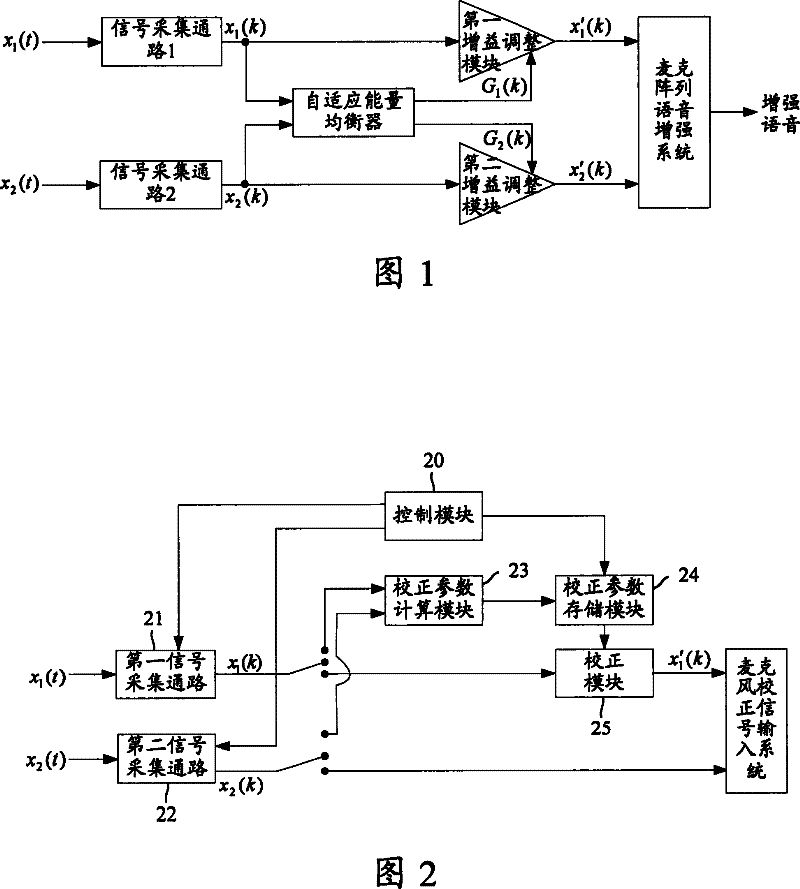
However, in practical applications, the microphone array may be located in the far-field area of ​​the sound source sound field, and may also be located in the near-field area of ​​the sound source sound field. When the distance between the sources is large, the pressure generated by the sound source on each microphone will be different. Therefore, adjusting the short-term average energy of the output signals of the two signal acquisition channels to the same value cannot accurately reflect the pressure of each microphone. Actual difference in input signal
[0014] 2. The cost of hardware implementation is high
[0015] In order to obtain a better correction effect, an input signal with a length of about 1 second is generally used when calculating the short-term average energy of the input signal. For speech signals, the sampling frequency is generally above 8000 Hz, so a large data buffer space is required , and the square root and division operations are used when calculating the short-term average energy and gain, which requires a strong computing power on the digital signal processing (DSP) chip, resulting in high cost
[0016] 3. It can only correct the amplitude characteristic difference between each signal acquisition channel, but it can't do anything about the phase characteristic difference between each signal acquisition channel
Due to problems in hardware design and other aspects, in the actual array system, the output signal of one signal acquisition channel is ahead of the output signal of another signal acquisition channel by one or more sample points. At this time, if only simple amplitude correction is performed, the microphone array The performance of the system still cannot meet the requirements
[0018] Fourth, it is necessary to correct the signal output by the signal acquisition channel in real time, which increases the amount of computation of the system

Method used


Image

  • System apparatus, device and method for correcting microphone
  • System apparatus, device and method for correcting microphone
  • System apparatus, device and method for correcting microphone

Examples


Embodiment Construction

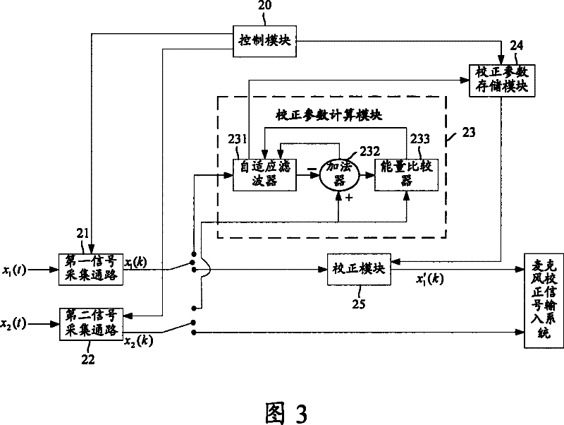
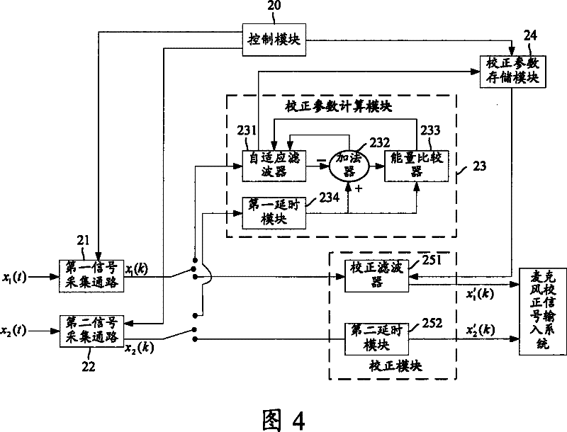
[0060] When the sound waves emitted by the sound source generate the same pressure on the microphone transducers at the same moment, the input signals of the signal acquisition channels corresponding to the microphones are the same. Taking signal acquisition channel 1 and signal acquisition channel 2 as examples, set the input signals of the two channels as x(t), and set the ideal sampling signal of x(t) as x(k), and use each signal acquisition channel as A system has:

[0061] x 1 (z)=X(z)H 1 (z)

[0062] x 2 (z)=X(z)H 2 (z)

[0063] Among them, X(z) is the signal obtained by transforming x(k) through Z, and H 1 (z) is the system response signal of signal acquisition channel 1, H 2 (z) is the system response signal of signal acquisition channel 2, X 1 (z) is the signal x output by the signal acquisition channel 1 1 (k) The signal obtained by Z transformation, X 2 (z) is the signal x output by the signal acquisition channel 2 2 (k) Signal obtained by Z transformatio...


PUM


Abstract

The invention discloses a microphone correction system including: a first and a second signal collecting accesses, calculating module, a memory module of correction parameters and a correction module. The correction method includes that when the startup condition calculated by correction parameters is appeased, it filters the signals output from the first access adaptively according to the reference signals from the second signal collecting access. Correction parameters taken from wave filter coefficients when the adaptive filter is constringed correct the signals from the first collecting access. The correction device consists of calculating and memory modules of correction parameters.

Description

technical field [0001] The invention relates to the technical field of speech signal processing, and in particular to a microphone correction system, device and method in a microphone array system. Background technique [0002] Microphone array technology is widely used in speech enhancement and other fields. Due to the use of spatial filtering technology, the voice enhancement effect of the microphone array system is often better than that of the single microphone system, but this is based on the premise that the characteristics of the signal acquisition channels of the microphone array system are highly consistent. In practical applications, due to cost considerations, microphones and electronic components with large dispersion of characteristics are often used to form the signal acquisition channels of the microphone array system, and the characteristics of microphones and electronic components will vary with time, temperature, humidity and other external factors. As a r...

Claims


Application Information

Patent Timeline
Patent Type & Authority Patents(China)
IPC IPC(8): H04R29/00
Inventor 邓昊冯宇红
Owner VIMICRO ELECTRONICS CORP
Why Eureka
Eureka Blog
Learn More