Gas flow measuring apparatus
A gas flow meter and detection element technology, applied in the field of flow meters, can solve problems such as characteristic changes, high cost, and deformation of the diaphragm, and achieve the effects of reducing stress transmission, cost does not increase, and the degree of freedom increases
- Summary
- Abstract
- Description
- Claims
- Application Information
AI Technical Summary
Problems solved by technology
Method used
Image
Examples
no. 1 approach
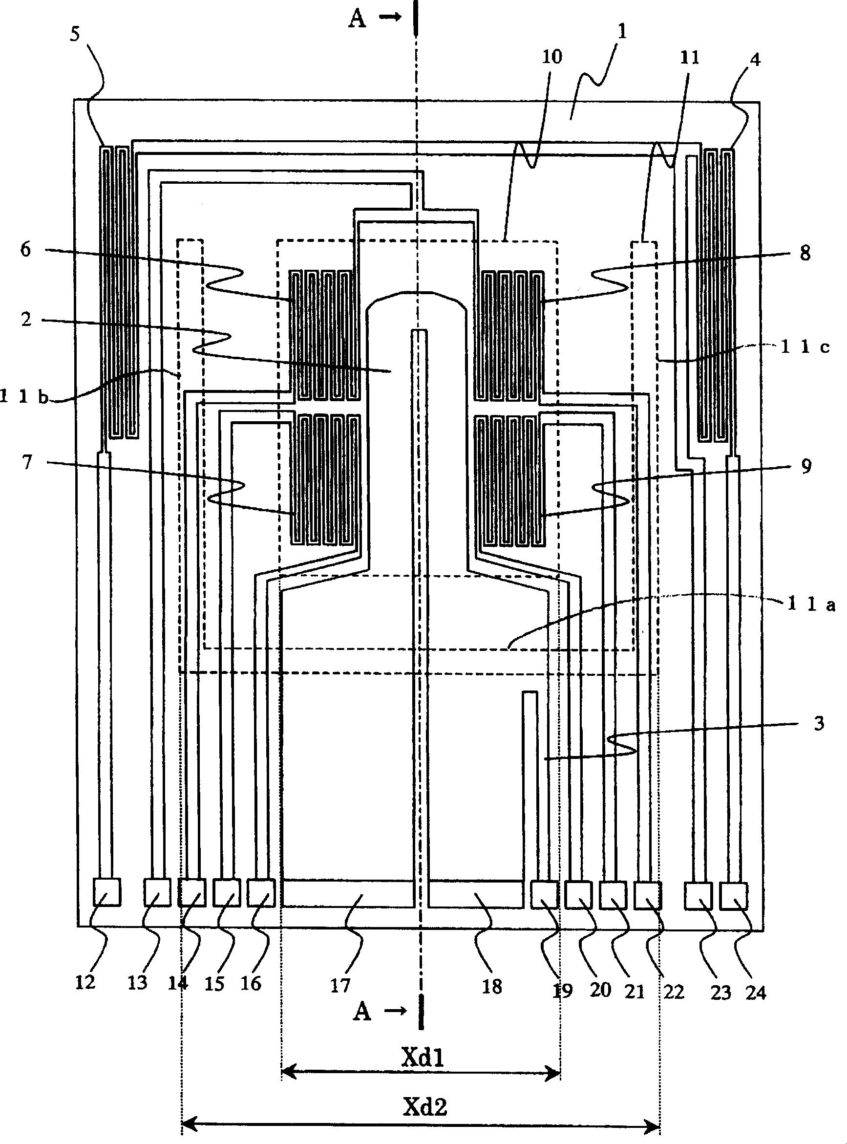
[0038] figure 1 It is a figure which shows the planar structure of the flow detection element in the air flow measuring device which concerns on 1st Embodiment of this invention. again, figure 2 is along figure 1 Sectional view of line A-A.
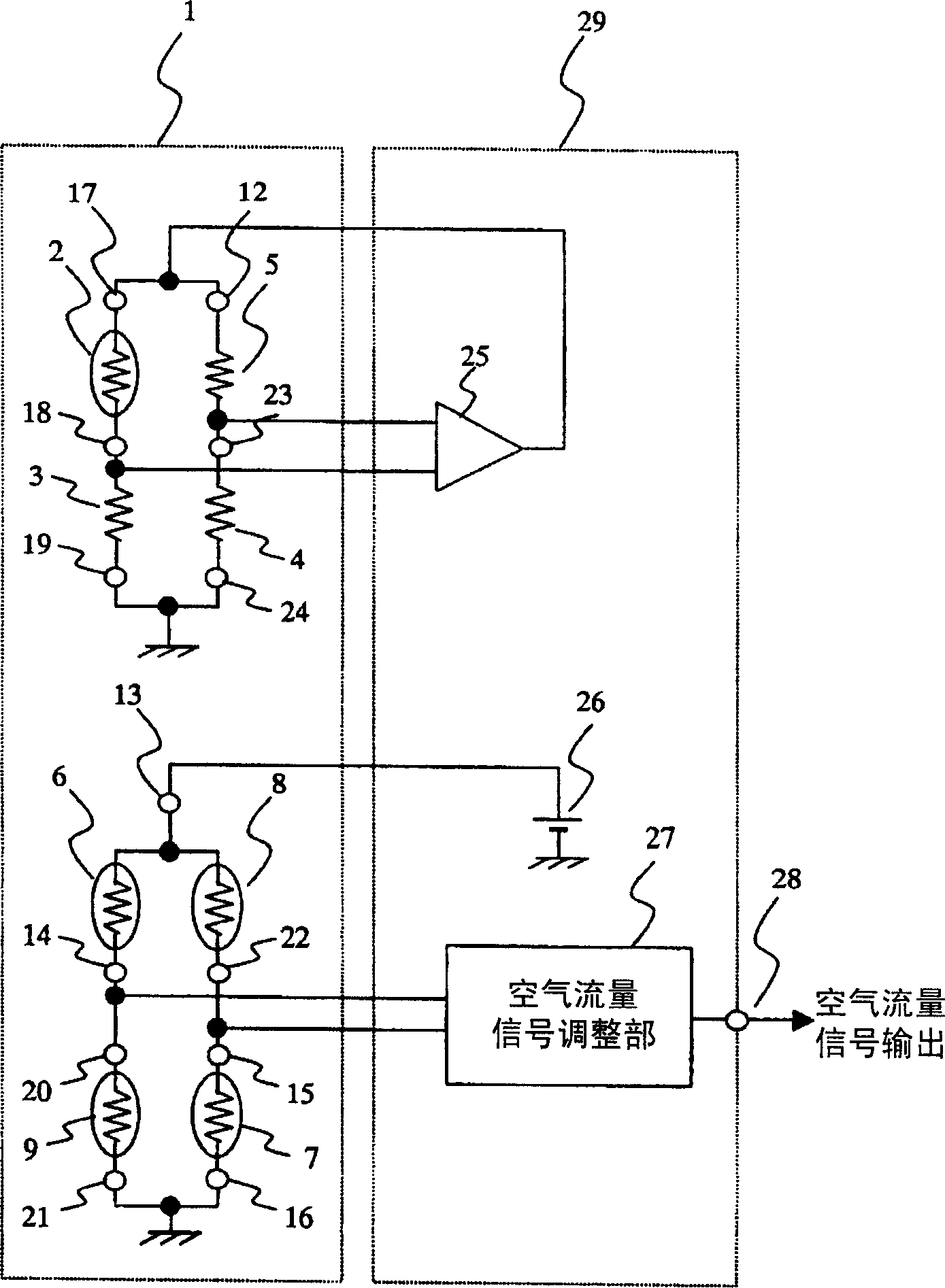
[0039] exist figure 1 as well as figure 2 In the detection element 1, the diaphragm 10 for air flow detection processed by etching with an alkali solvent or the like is formed with a horizontal length Xd1 (outer diameter dimension of the diaphragm) in the figure from the back of the substrate (first substrate). . Further, on the diaphragm 10 , the heating resistor 2 as a detection resistor, the upstream temperature-sensing resistors 6 and 7 , and the downstream temperature-sensing resistors 8 and 9 are arranged.
[0040] Fixed resistors 3 and 4 and a temperature measuring resistor 5 are formed on a substrate around the diaphragm 10 . These resistors are made of platinum or polysilicon films whose resistance value changes with tem...
no. 2 approach
[0062] Figure 7 It is a figure which shows the planar structure of the flow detection element in the air flow measurement apparatus of 2nd Embodiment of this invention. This second embodiment is, as opposed to figure 1 In the first embodiment shown, the shape of the groove 11 is changed from a "U" shape to an "I" shape, so that only the horizontal groove 11a is provided. other structures with figure 1 The same example.
[0063] because by doing as it should Figure 7 The groove shape shown can reduce the mounting stress with the necessary minimum processing area, so the influence of strain can be suppressed without reducing the strength.
no. 3 approach
[0065] Figure 8 It is a figure which shows the planar structure of the flow detection element in the air flow measurement apparatus of the 3rd Embodiment of this invention, Figure 9 is for the air flow measuring device of the third embodiment, along Figure 4 Sectional view of the B-B line.
[0066] The third embodiment, with respect to such as figure 1 In the first embodiment shown, the shape of the groove 11 is changed from a "U" shape to surround the diaphragm 10, and a horizontal groove 11d is added. Other structures like figure 1 The example shown is the same.
[0067] By adopting such a groove shape, the bonding part (fixed part) of the detection element is not only a part where the terminals 12 to 24 are formed, such as Figure 9 As shown, the front end of the detection element 1 (the end region opposite to the fixed region across the diaphragm 10 and the lateral groove 11 d ) is also fixed to the substrate 56 with the adhesive 64 , and the influence of strain ca...
PUM
 Abstract
Description
Claims
Application Information
 - R&D
- Intellectual Property
- Life Sciences
- Materials
- Tech Scout
- Unparalleled Data Quality
- Higher Quality Content
- 60% Fewer Hallucinations
Browse by: Latest US Patents, China's latest patents, Technical Efficacy Thesaurus, Application Domain, Technology Topic, Popular Technical Reports.
© 2025 PatSnap. All rights reserved.Legal|Privacy policy|Modern Slavery Act Transparency Statement|Sitemap|About US| Contact US: help@patsnap.com


