
Method for projecting and screening microelectronic-packed tin ball

A screening method and tin ball technology, applied in chemical instruments and methods, solid separation, classification, etc., can solve the problems of low screening efficiency, multi-row overlap, low screening accuracy, etc., and achieve high screening efficiency, low probability of missed detection, The effect of high screening accuracy

Inactive Publication Date: 2007-01-17
安徽精通科技有限公司
View PDF1 Cites 24 Cited by
  • Summary
  • Abstract
  • Description
  • Claims
  • Application Information

AI Technical Summary

Problems solved by technology

However, screening with rollers has the following disadvantages: 1. The impact of the bearing clearance of the rollers results in low screening accuracy; 2. When the solder balls flow, it is easy to have multiple rows of overlapping phenomenon, causing the small balls to overlap on the big balls, resulting in missed inspections ;3. The solder balls are easy to stick to the rollers, and the scraper cannot be scraped cleanly, and the solder balls are brought down and squeezed and deformed; 4. The screening efficiency is low
Extensive searches have been carried out for the above problems, but no ideal technical solutions have been found

Method used


Image

  • Method for projecting and screening microelectronic-packed tin ball
  • Method for projecting and screening microelectronic-packed tin ball

Examples


Embodiment 1

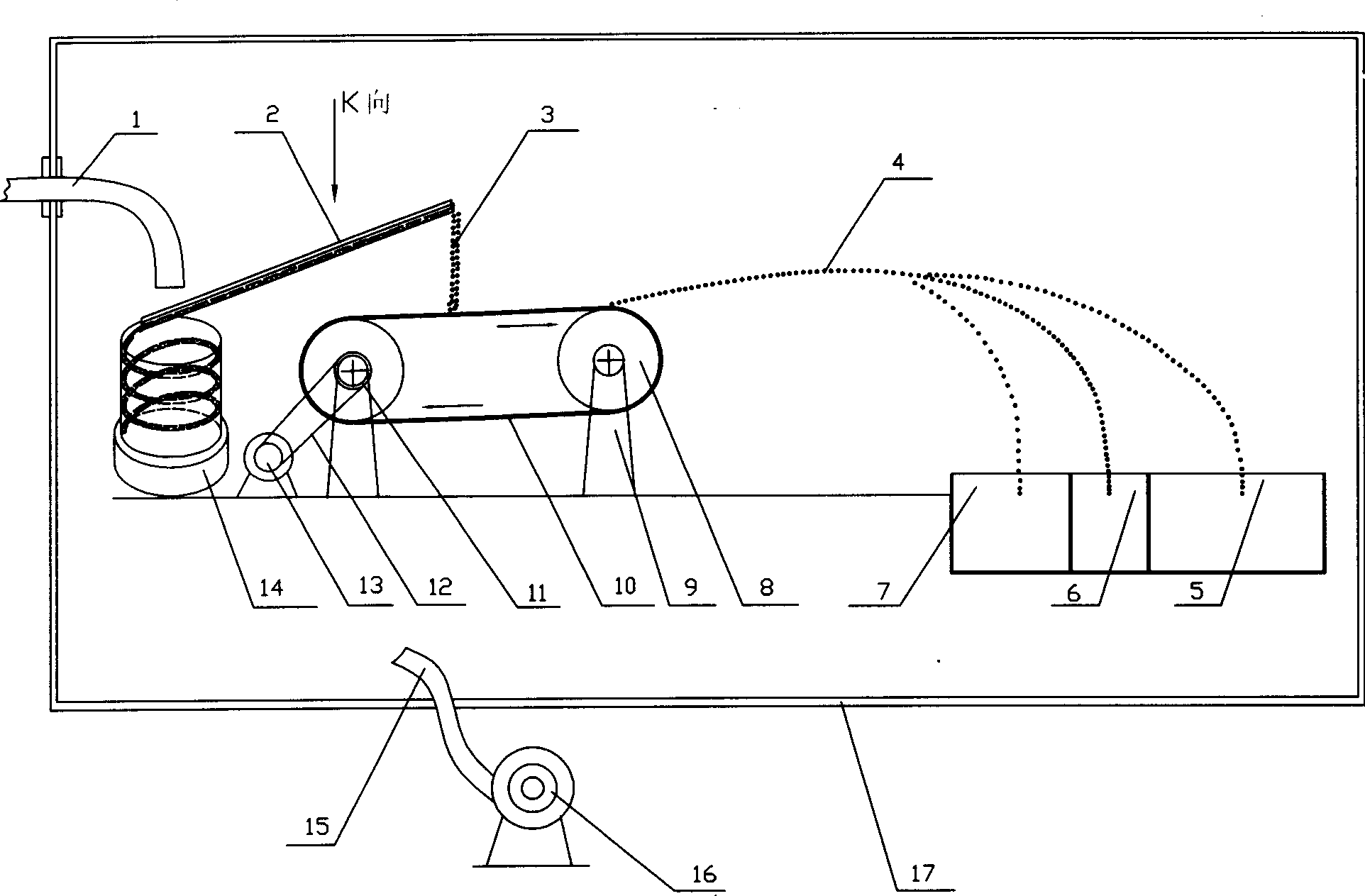
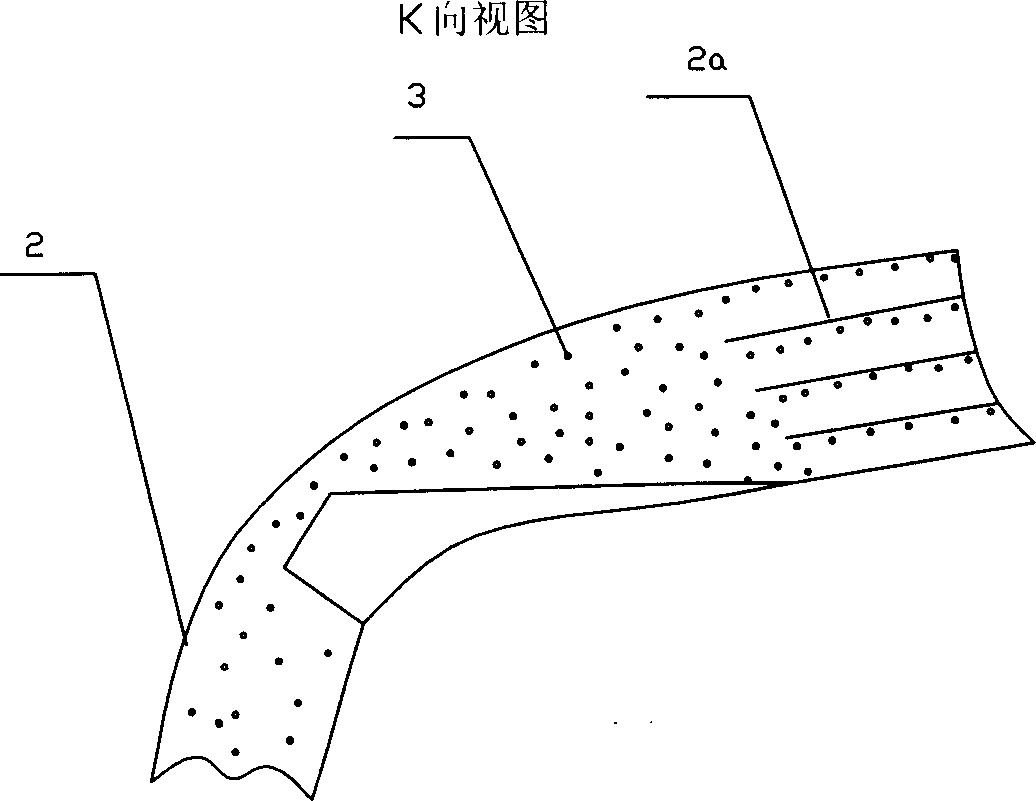
[0011] Embodiment 1: as figure 1 Shown, a mechanical vibrating screw feeding device 14 is set on the supporting surface in the vacuum cover 17, and vibrating feeding hopper 2 is connected above it, and the feeding hopper 2 is provided with sub-discharging passage 2a (as figure 2 shown), in order to make the solder balls 4 oscillate in a single row along the sorting channel 2a. Also be provided with a motor 13 and a pair of drive roller 8 on the support surface, drive roller 8 is connected on the support surface by support frame 9, the output shaft of motor 13 is connected with the synchronous pulley 11 on the drive roller by synchronous belt 12 Connection and cooperation, the transmission roller is connected with a conveyor belt 10, and the mouth of the feed hopper 2 is matched with the middle of the conveyor belt 10, so that the solder balls will not fall into the conveyor belt. The conveyor belt 10 can have a certain upward inclination angle, and the solder balls 3 is thro...


PUM


Abstract

A throwing method for screening the tin beads used for microelectronic package features that its thrower is composed of a vibration-type spiral feeder, a throw unit consisting of motor, drive roller and conveying belt, three recepting boxes and a vacuum cover with vacuumizing pump.

Description

Technical field: [0001] The invention relates to a screening method for solder balls in microelectronic packages. Background technique: [0002] With the rapid development of electronic information technology, the use of large-scale integrated circuits is increasing, and the IC chips need to be packaged with solder balls, which requires the manufacture of a large number of high-quality solder balls. In the existing solder ball production process, the prepared solder balls need to be screened by two pairs of rollers with different gaps to screen out genuine solder balls and oversized and undersized solder balls. However, screening with rollers has the following disadvantages: 1. The impact of the bearing clearance of the rollers results in low screening accuracy; 2. When the solder balls flow, it is easy to have multiple rows of overlapping phenomenon, causing the small balls to overlap on the big balls, resulting in missed inspections ; 3. The solder balls are easy to stick...

Claims


Application Information

Patent Timeline
Patent Type & Authority Applications(China)
IPC IPC(8): B07B13/11B07B13/16
Inventor 鲍复鱼郝世浩
Owner 安徽精通科技有限公司
Learn More