Eureka AIR delivers breakthrough ideas for toughest innovation challenges, trusted by R&D personnel around the world.

Cutting method for laminated body and cutting knife used therein

A laminated body and cutter technology, applied in metal processing and other directions, can solve problems such as damage to the surface of brittle material substrates, and achieve the effect of prolonging the service life and preventing rotation

Inactive Publication Date: 2009-07-22
MITSUBOSHI DIAMOND IND CO LTD
View PDF2 Cites 31 Cited by
  • Summary
  • Abstract
  • Description
  • Claims
  • Application Information

AI Technical Summary

Problems solved by technology

[0007] However, in the above-mentioned cutting method, peeling pieces of the resin film inevitably occur.
Also, when a squeegee is inserted between the brittle material substrate and the resin film for relative movement, the surface of the brittle material substrate may be damaged by the squeegee.

Method used


Image

  • Cutting method for laminated body and cutting knife used therein
  • Cutting method for laminated body and cutting knife used therein
  • Cutting method for laminated body and cutting knife used therein

Examples


Embodiment 1

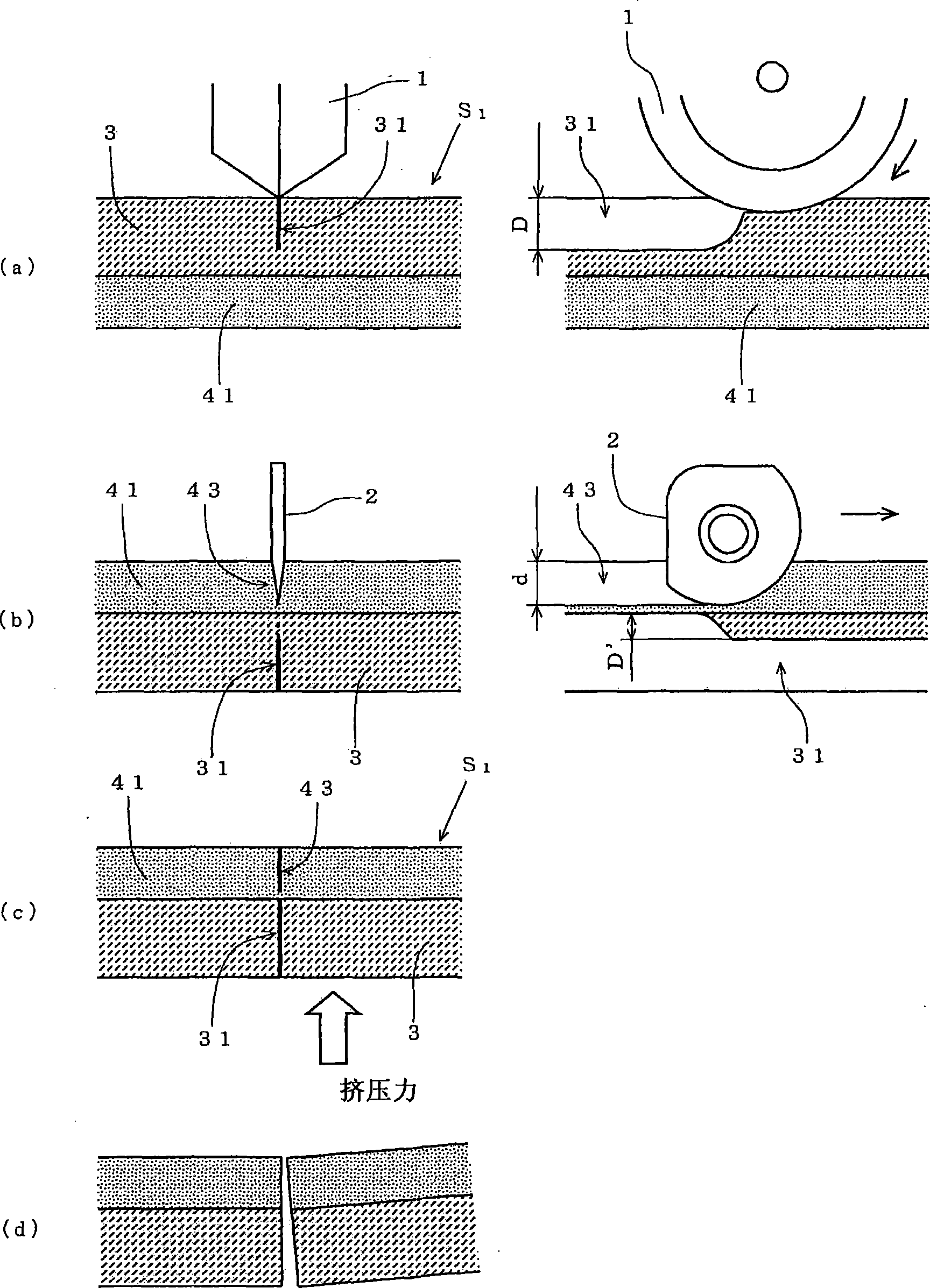
[0076] On one side of a glass substrate made of soda lime glass (soda lime) with a thickness of 1.1 mm, a first PET (polyethylene terephthalate) film with a thickness of 0.2 mm is sequentially laminated from the glass substrate. The second PET film constitutes a laminated body. For such a laminated body, firstly, the cutting wheel is applied with a load of 0.14 MPa and pressed against the glass substrate, and moves relative to the glass substrate at a cutting speed of 300mm / sec to form on the glass substrate. Cutting line. The depth of the vertical crack formed at this time was 50% of the thickness of the glass substrate. In addition, the specifications of the cut-off wheel used are as follows.

[0077] Cutting Wheel Specifications:

[0078] Outer diameter: 2mm

[0079] Thickness: 0.65mm

[0080] Inner diameter: 0.8mm

[0081] Blade angle: 115°

[0082] Groove depth: 25μm

[0083] Ridgeline length between grooves: 25μm

[0084] Next, a cutter with a blade angle of 45° ...

Embodiment 2

[0087] For a laminate having the same structure as in Example 1 except that the thickness of the glass substrate is 0.55 mm, the thickness of the first PET film is 0.2 mm, and the thickness of the second PET film is 0.05 mm, the following specifications are cut The wheel applies a load of 0.1MPa and presses against the glass substrate, moves relative to the glass substrate at a cutting speed of 300mm / sec, and forms a cutting line on the glass substrate. The depth of the vertical crack formed at this time was 10% of the thickness of the glass substrate.

[0088] Cutting Wheel Specifications:

[0089] Outer diameter: 3mm

[0090] Thickness: 0.65mm

[0091] Inner diameter: 0.8mm

[0092] Blade angle: 130°

[0093] Groove depth: 3μm

[0094] Ridge length between grooves: 15μm

[0095] Next, a cutter with a blade angle of 30° was pressed against the second PET film with a load of 0.4 MPa, and the cutter was moved relative to the laminate to completely cut the second PET film ...


PUM

PropertyMeasurementUnit
thicknessaaaaaaaaaa
thicknessaaaaaaaaaa
thicknessaaaaaaaaaa

Abstract

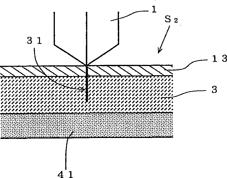
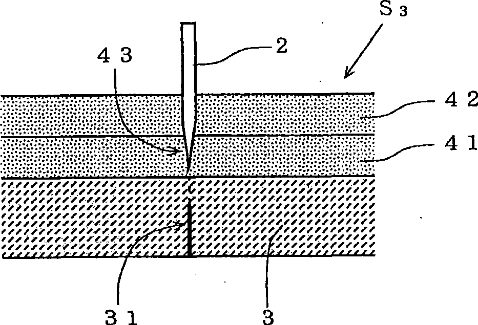
The invention provides a cutting off method of a laminated body and a cutting tool used therein. In the cutting process of the laminated body in which fragile material and resin films are laminated, no waste, such as stripped pieces or broken pieces, is generated, and the surface of the fragile material substrate will not be damaged. From the surface of the glass substrate (3), which is contrary to the resin film, cracks (31) with thickness of between 10% and 100% of the thickness of the glass substrate (3), which is substantial perpendicular to the glass substrate surface, are formed. Then, the cutting tool (2) is pressed at or near the position of the resin film (41) surface corresponding to the cracks (31), the cutting tool (2) moves corresponding to the laminated body (S1), thereby a cut (43) is formed on the resin film (41), the cut (43) has a thickness of more than 90% of the thickness of the resin film (41) and does not reach the range of the glass substrate (3).

Description

technical field [0001] The present invention relates to a method for cutting a laminated body in which a brittle material substrate and a resin film are laminated, and a cutting blade used in the method. Background technique [0002] Since brittle material substrates such as glass and ceramics are mechanically brittle, the cutting of brittle material substrates, for example, forms a scribe line (Scribe Line) on the surface of the substrate by making a cutting wheel (cutter wheel) press-contact and roll on the substrate. This generates cracks in the vertical direction from the surface of the substrate (cutting process), and then applies stress to the substrate to grow the vertical cracks to the rear surface of the substrate (fracture process), thereby cutting the substrate. [0003] On the other hand, the resin film generally has flexibility or ductility, so the cutting of the resin film, for example, is achieved by the frictional shearing action of two hard metal blades with...

Claims


Application Information

Patent Timeline
Patent Type & Authority Applications(China)
IPC IPC(8): B26D3/00B26D1/25
Inventor 中垣智贵前川和哉
Owner MITSUBOSHI DIAMOND IND CO LTD
Why Eureka
Eureka Blog
Learn More