Communication control system
一种通信控制、通信站的技术,应用在传输系统、数字传输系统、安全通信装置等方向,能够解决兼容性不够、不能充分满足开放协议通信要求、不能充分地满足实时性和可靠性等问题
- Summary
- Abstract
- Description
- Claims
- Application Information
AI Technical Summary
Problems solved by technology
Method used
Image
Examples
no. 1 example
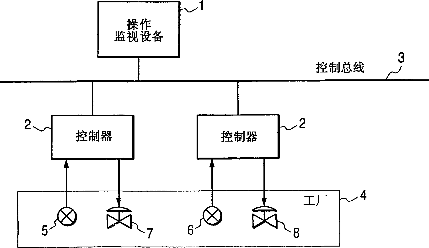
[0124] figure 2 is a block diagram outputting one embodiment of the present invention. exist figure 2 In this case, the communication path 10 is double-multiplexed by the primary path 11 and the secondary path 12 . Communication path 10 is, for example, a control bus of a distributed control system.
[0125] The communication station 20 and the communication stations 31 to 3N are connected to the main path 11 and the sub path 12 .
[0126] The communication station 20 includes a unit 21 for performing communication. figure 1 The embodiments in include a single unit.
[0127] In unit 21, high priority communication section 211 performs high priority communication. The low priority communication section 212 performs low priority communication.
[0128] High-priority communication transmits process data, operating quantities, and alarms, etc. Low-priority communication performs image data transfer, file transfer, and message transfer, etc. High-priority communication tr...
no. 3 example
[0153] Figure 5 is a block diagram showing another embodiment of the present invention.
[0154] exist Figure 5 In , the communication station 40 is connected to the main path 11 and the secondary path 12 .
[0155] The high priority communication section 401 performs high priority communication by using the main path 11 .
[0156] The low priority communication section 402 performs low priority communication by using the sub path 12 .
[0157] The path diagnosis section 403 diagnoses the soundness of the main path 11 and the sub path 12 .
[0158] According to the diagnosis result of the path diagnosis section 403, the switching section 404 switches the communication path between the high-priority communication section 401 and its remote communication partner.
[0159] The restriction section 405 restricts communication by the low priority communication section 402 according to the diagnosis result of the path diagnosis section 403 . For example, the restriction sectio...
no. 4 example
[0172] Figure 6 is a block diagram showing another embodiment of the present invention. Figure 6 A specific structural example of the path diagnosis section is shown.
[0173] exist Figure 6 Among them, the path state storage section 501 stores path state information on whether the communication path originating from the local station is intact at each interface and at each remote station.
[0174] The sending part 502 receives a sending request from the high-priority communication part 401, refers to the path state information in the path state storage part 501, selects a good communication path, and sends data on the communication path.
[0175] In a case where a normal reception response is not received within a predetermined time after data transmission, transmission section 502 assumes that the communication path has failed, and reflects this information to path status information in path status storage section 501 .
[0176] The reception section 503 receives data ...
PUM
 Abstract
Description
Claims
Application Information
 - R&D Engineer
- R&D Manager
- IP Professional
- Industry Leading Data Capabilities
- Powerful AI technology
- Patent DNA Extraction
Browse by: Latest US Patents, China's latest patents, Technical Efficacy Thesaurus, Application Domain, Technology Topic, Popular Technical Reports.
© 2024 PatSnap. All rights reserved.Legal|Privacy policy|Modern Slavery Act Transparency Statement|Sitemap|About US| Contact US: help@patsnap.com


