
Apparatus and method for face/iris combination optical imagine

An optical imaging and iris technology, applied in computer parts, instruments, character and pattern recognition, etc., can solve the problems of high cost, sensitive to interference, huge amount of calculation, etc., to achieve high cost performance, fewer motor movements, high reliability and stability The effect of service life

Active Publication Date: 2007-01-10
SUZHOU SIYUAN KEAN INFORMATION TECH
View PDF0 Cites 51 Cited by
  • Summary
  • Abstract
  • Description
  • Claims
  • Application Information

AI Technical Summary

Problems solved by technology

The disadvantages are: high consistency requirements for two sets of wide-angle camera parameters, complex camera calibration, facial feature extraction and facial image matching are sensitive to noise interference, require a huge amount of calculation, and the speed is difficult to achieve real-time frame rate (requires professional real-time machines vision processor), measurement accuracy, reliability and stability are sensitive to interference, and the cost of this method alone is more expensive than traditional iris optical imaging devices
[0004] 1 The optical imaging device system cannot obtain the highest quality iris texture image;
[0005] 2 The optical imaging device system has the problem of quickness of use, such as requiring more than 2 seconds;
[0006] 3 The optical imaging device system has usability problems, such as requiring strict cooperation from users;
[0007] 4. The optical imaging device system does not have high reliability and stability. For example, it cannot be used outdoors, with strong backlight, strong halogen light, and wide temperature range;
[0008] 5 The optical imaging device system is not cost-effective;
[0009] In addition, there is a lack of objective and unified technical standards as a comprehensive performance evaluation system

Method used


Image

  • Apparatus and method for face/iris combination optical imagine
  • Apparatus and method for face/iris combination optical imagine
  • Apparatus and method for face/iris combination optical imagine

Examples


Embodiment 1

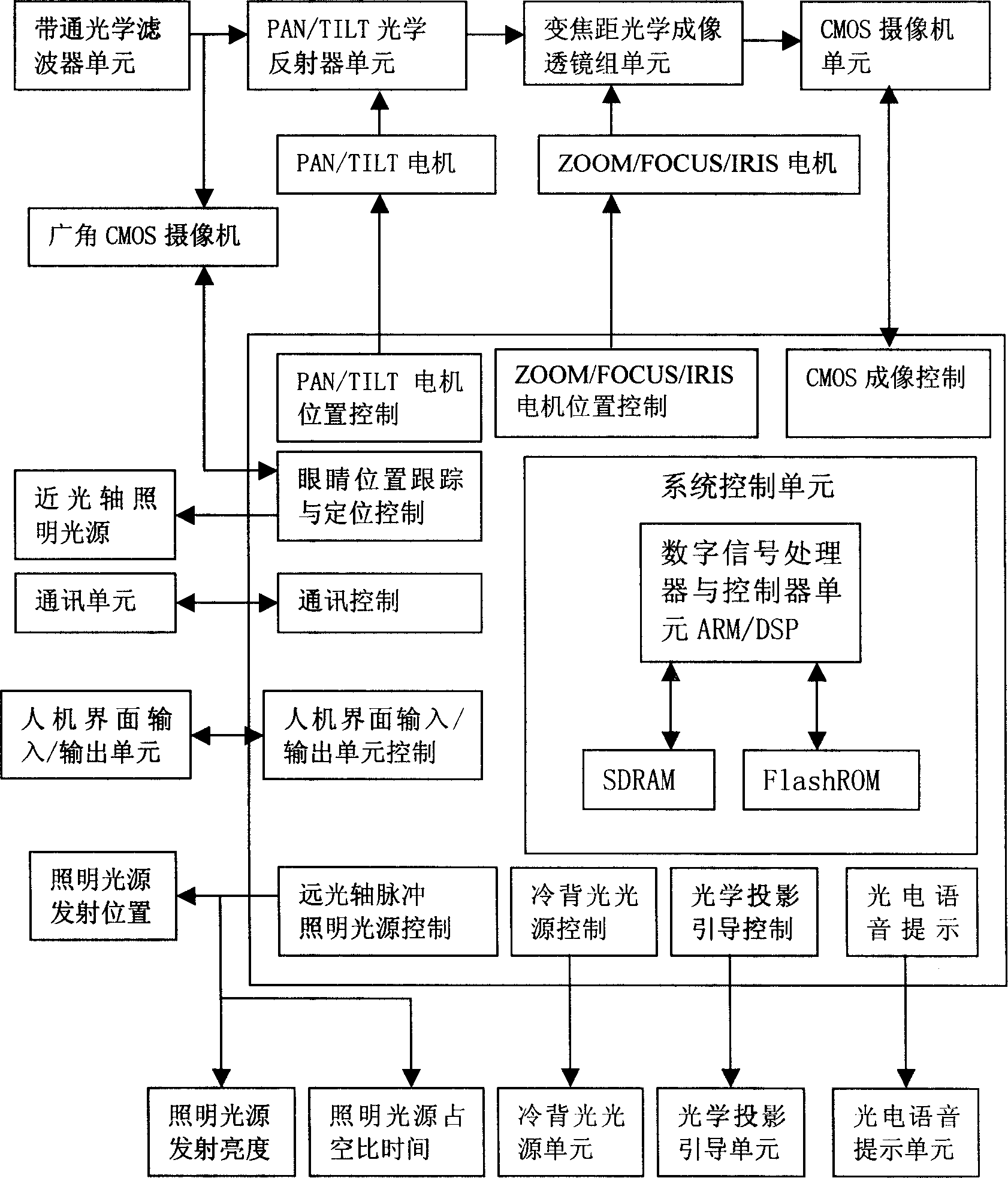
[0116] figure 1 The specific structure of the system of Embodiment 1 of the present invention is described. It includes the following functional units: band-pass optical filter unit, PAN / TILT optical reflector unit, zoom optical imaging lens unit, CMOS camera unit, and eye position positioning unit , Communication unit, human-machine interface input / output unit, high beam axis pulsed illumination light source unit, cold backlight light source unit, working area (field of view) optical projection guide beam unit, photoelectric voice prompt unit, digital signal processor and controller unit , And system control unit.

[0117] The system control unit includes:

[0118] (1) PAN / TILT optical reflector PAN / TILT motor position control; (2) zoom optical imaging lens group ZOOM / FOCUS / IRIS motor position control; (3) high beam axis pulse illumination light source position POSITION, emission brightness L, Duty cycle time T control (triggered synchronously with the CMOS camera integration t...

Embodiment 2

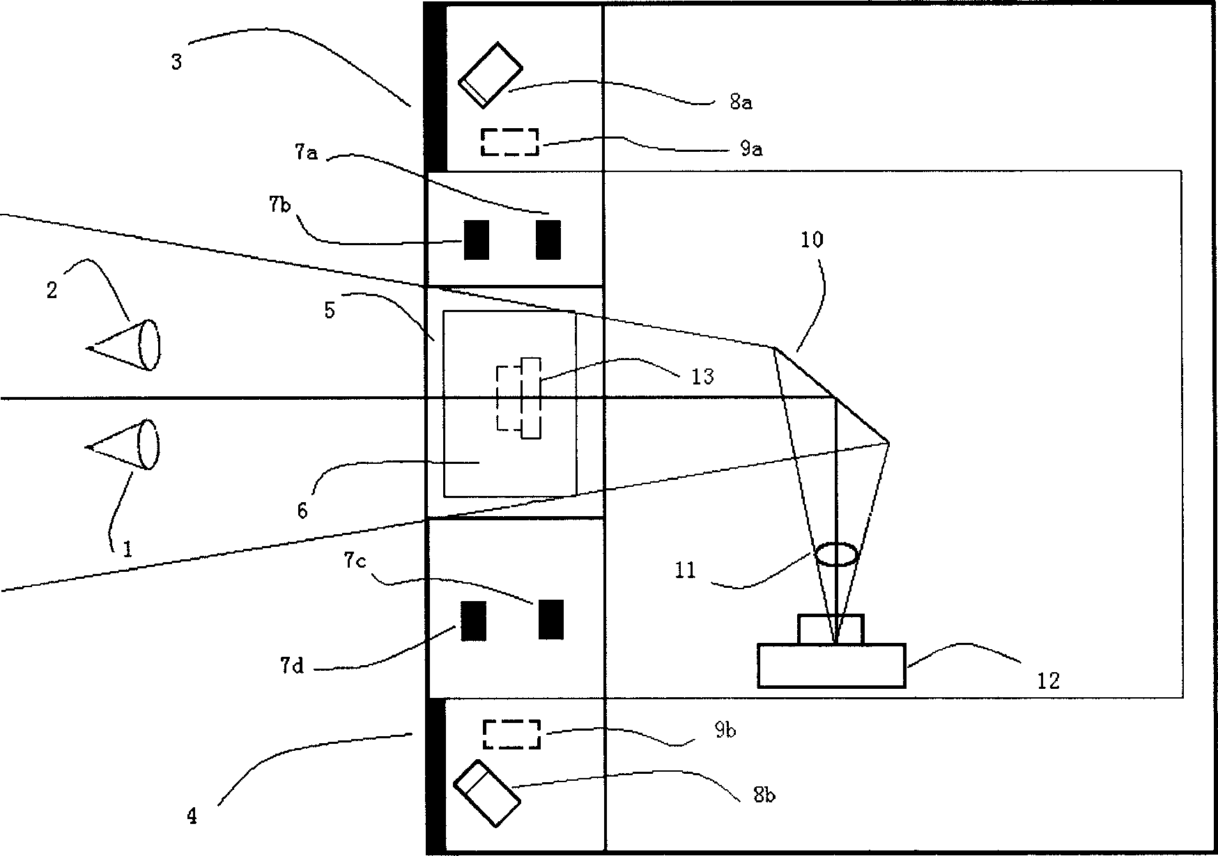
[0481] Specific embodiment of the present invention 2 imaging optical principle of optical imaging device Picture 12 , Including the following units: near-infrared diffuser (3, 4), cold backlight light source (5), PAN / TILT band-pass optical filter (6), working area (field of view) optical projection guide beam (7a, 7b, 7c, 7d), high beam axis pulsed illumination light source (8a, 8b), zoom optical imaging lens group (11), CMOS camera (12), low beam axis illumination light source (9a, 9b), optical reflector ( 21), guide indicators (15a, 15b), all-pass optical filter (22), wide-angle CMOS camera (13). (1, 2) are left and right eyes. The PAN / TILT bandpass optical filter (6) is composed of a PAN / TILT optical reflector and a bandpass optical filter. The bandpass optical filter reflects visible light and transmits near-infrared light.

[0482] The eye position positioning information (x, y, z) is realized by a face imaging optical path system formed by a combination of a near optical a...

Embodiment 3

[0485] The four typical optical path equivalent conversion or optical path deformation methods of specific embodiment 3 are combined with each other, and operations such as modification, addition, and reduction are used to implement specific embodiments. The purpose is to enable professionals in the technical field to be able to perform the same or equivalent Use within the scope of understanding. It can be understood that the equivalent transformation of the optical path changes the propagation direction of the optical path.

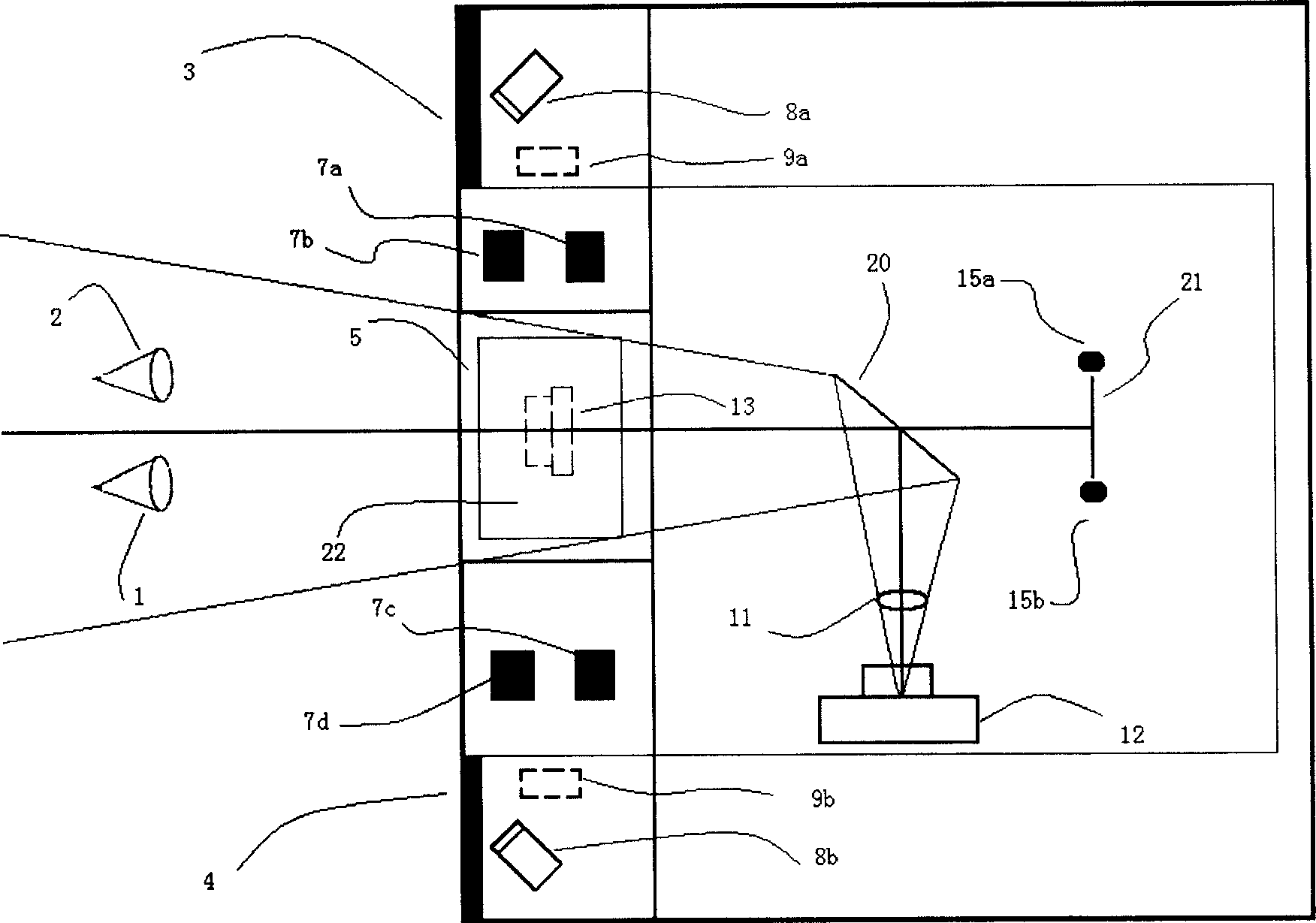
[0486] (One). Figure 4 Describes the imaging optics principle diagram of the optical imaging device of specific embodiment 3 of the present invention, which includes the following units: near-infrared light diffuser (3, 4), cold backlight light source (5), band-pass optical filter (6) ), working area (field of view) optical projection guiding light beam (7a, 7b, 7c, 7d), high beam axis pulsed illumination light source (8a, 8b), variable focal length optica...


PUM


Abstract

The present invention discloses face / iris combination optical imaging device. It contains visible light imaging light path system, near infrared light imaging light path system, face imaging light path system; said face / iris combination optical imaging device including above-mentioned imaging light path systematical optical equivalent transformation. The present invention also provides face / iris combination optical imaging method, which contains eye position tracking and positioning, and obtaining maximum quality iris texture image. Said invented device and method can rapid obtain maximum quality iris texture image, and easy to use.

Description

Technical field [0001] The present invention relates to a device and method for providing face / iris combined imaging, in particular to a device and method for obtaining optical imaging of a face / iris image under conditions that meet objective unified technical standards. Background technique [0002] Relevant patent literature search USPTO database includes: US6594377, US 6785406, US6832044, US 20020191075, US20020191076, US20030012413, US20030021598, US 20030081817, US20030219247, US 20050084137, US 20050084179. The above-mentioned related patent documents use two sets of stereo cameras to obtain eye position positioning information through stereo vision technology. The method includes facial image acquisition, camera calibration, facial feature extraction, facial image matching and other steps to perform complex machine vision calculations. The disadvantages are: high requirements for the consistency of the parameters of the two sets of wide-angle cameras, complex camera calibr...

Claims


Application Information

Patent Timeline
Patent Type & Authority Applications(China)
IPC IPC(8): G06K9/00
Inventor 金城
Owner SUZHOU SIYUAN KEAN INFORMATION TECH
Learn More