
System and method for filling a vessel with a gas or a gas mixture

A technology of filling gas and mixture, which is applied in the method of container discharge, container filling method, and equipment loaded into pressure vessels, etc., which can solve the problems of difficult operation of filling gas and impossibility of accurate calibration, etc., and achieve the effect of preventing evaporation

Inactive Publication Date: 2006-11-01
MESSER GRIESHEIM GMBH
View PDF3 Cites 16 Cited by
  • Summary
  • Abstract
  • Description
  • Claims
  • Application Information

AI Technical Summary

Problems solved by technology

[0004] But in the process of filling with liquefied gas, the following problem arises, that the operation of filling gas in the state of boiling point is very difficult
In particular, the exact determination of the filled fuel quantity and thus the exact calibration of the mixing ratios of the individual gas components in the filled container is hardly possible in the case of filling gas mixtures

Method used


Image

  • System and method for filling a vessel with a gas or a gas mixture

Examples


Embodiment Construction

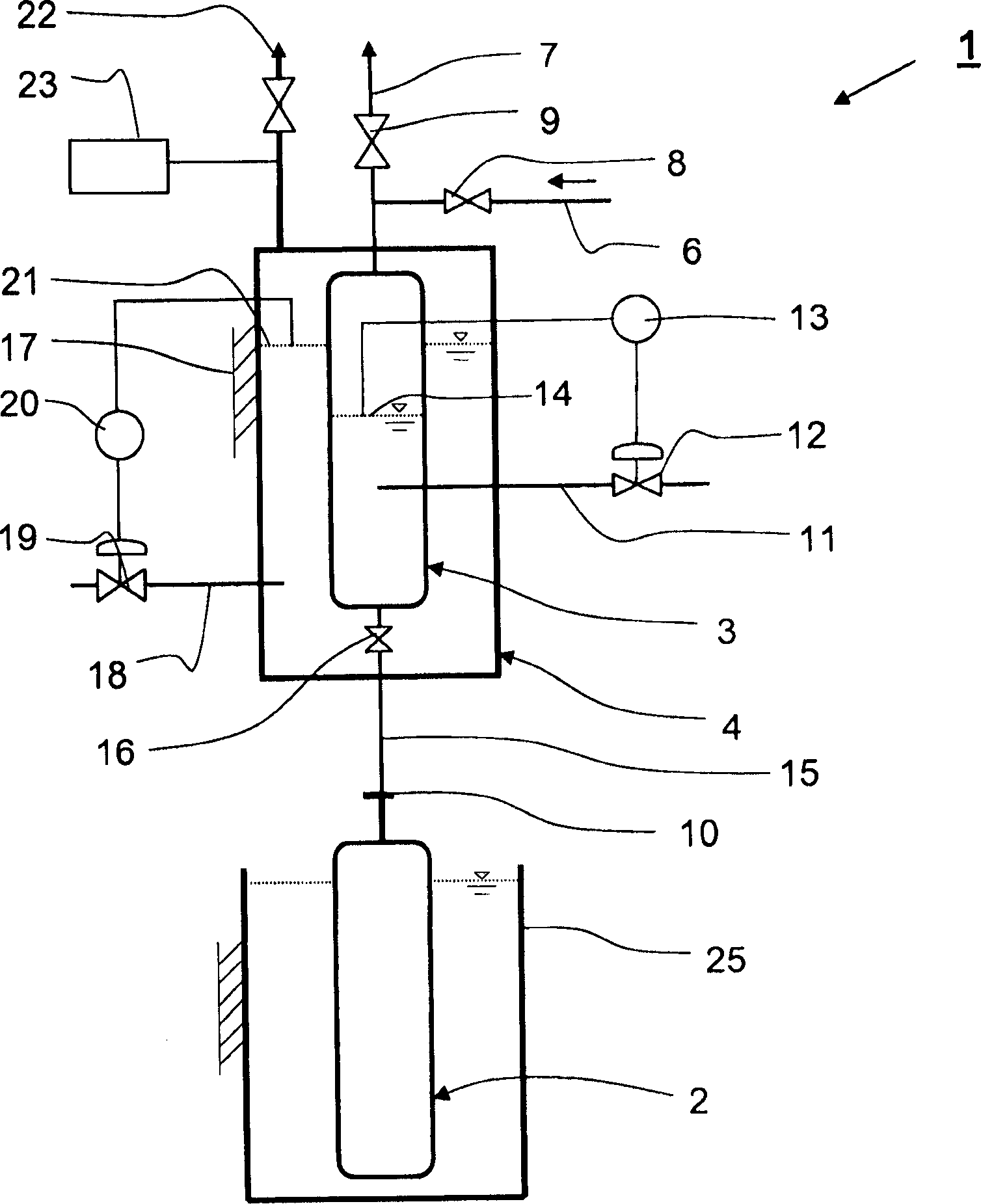
[0016] The device 1 for filling a container 2 with a filling gas or a filling gas mixture comprises a metering container 3 which is accommodated inside a pressure vessel 4 . In the upper region of the metering container, a gas feed line 6 for feeding gaseous filling gas opens into the metering container 3 . The gas inlet line 6 is connected to an exhaust line 7 . The gas inlet line 6 and the exhaust line 7 can be closed or opened via valves 8 , 9 . A liquid gas feed line 11 for feeding liquid filling gas opens into the central region of the metering container 3 . The liquid gas supply line 11 is provided with a valve 12 which can be controlled by means of a control device 13 as a function of a measured liquid level 14 inside the metering container 3 . Furthermore, the metering container 3 is equipped with a filling line 15 , which, in the operating state of the device 1 , creates a fluid connection for filling the container 2 via a detachable connecting device 10 . The fill...


PUM


Abstract

In a process to charge an airbag cartridge with a precisely-defined quantity of gas, the gas is introduced into the cartridge under thermal contact with a heat exchanger at a temperature which is lower than the boiling point, but higher than the freezing temperature. The temperature within the container is lower than that of the dosing container.

Description

technical field [0001] The invention relates to a method and a device for filling containers with a filling gas or a filling gas mixture. Background technique [0002] In order to be able to store gases with high storage densities, the storage takes place under high pressure either in the liquid state or in the gaseous state. Although storage in the liquid state achieves extremely high storage densities, it is only possible with more or less high evaporation losses, which are unavoidable even in well-insulated containers. For the pressure storage of gases, mainly air compressors are currently used, which allow operating pressures of approximately 200 to 300 bar in the pressure vessel. However, these air compressors are very complex in construction and operation, and new applications, for example in fuel cell technology or in gas generators for airbags, require much higher pressures of 700 bar or more. Such pressures cannot be achieved or can only be achieved with great exp...

Claims


Application Information

Patent Timeline
Patent Type & Authority Applications(China)
IPC IPC(8): F17C5/04
CPCF17C5/06F17C7/04F17C13/021F17C2221/016F17C2221/017F17C2223/0161F17C2223/033F17C2223/046F17C2225/0123F17C2225/036F17C2225/046F17C2227/0341F17C2227/0383F17C2250/0408F17C2250/0626F17C2250/0631F17C2260/025F17C2270/05
Inventor H·格拉布霍恩F·赫尔佐克
Owner MESSER GRIESHEIM GMBH
Learn More