
Parallel-in inverter current control method adopting filter intermediate current feed-back

An intermediate current and current control technology, applied in the direction of single-network parallel feeding arrangement, etc., can solve the problems of limiting output current steady-state error harmonic suppression ability, power grid voltage distortion and harmonic interference, small open-loop gain, etc., to achieve Good dynamic response characteristics, low output current waveform distortion, and small steady-state error

Inactive Publication Date: 2006-10-25
ZHEJIANG UNIV
View PDF0 Cites 32 Cited by
  • Summary
  • Abstract
  • Description
  • Claims
  • Application Information

AI Technical Summary

Problems solved by technology

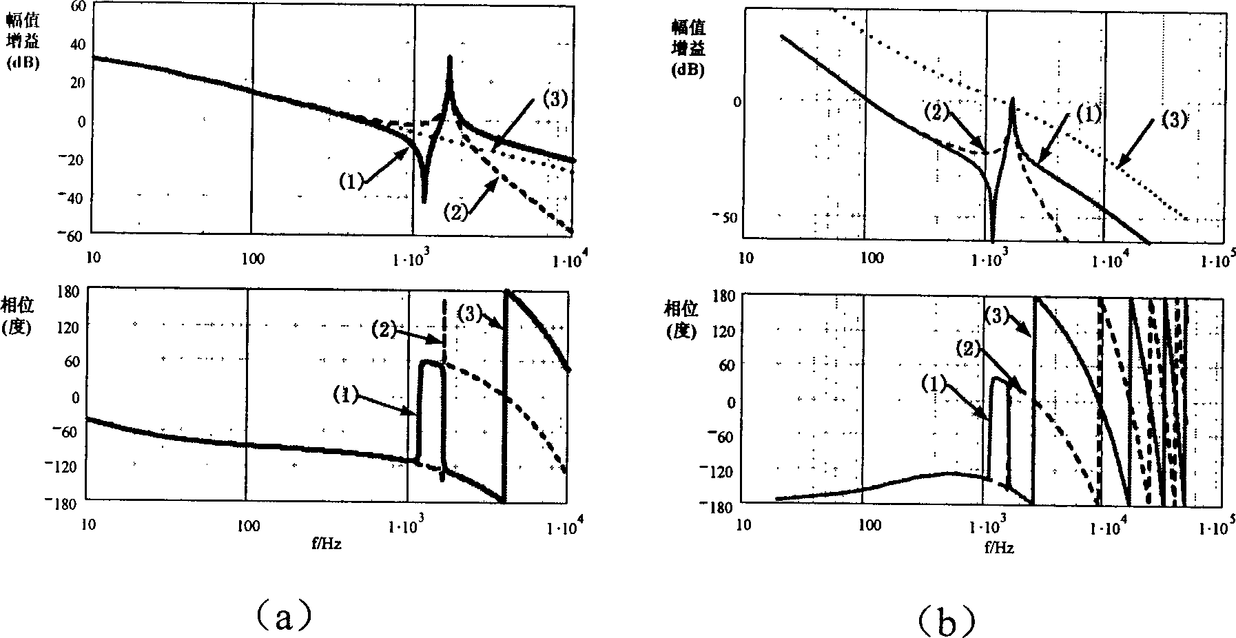
Because the filter of LCL structure makes the control object a third-order system, there is a large gain peak near the corner frequency of the filter. In order to ensure the stability of the system, the gain of the proportional-integral regulator is limited and the value is small, so that the system is in The open-loop gain in the low frequency band is small, which limits the ability of the system to suppress output current steady-state errors and harmonics
This method is also susceptible to grid voltage distortion and harmonic interference

Method used


Image

  • Parallel-in inverter current control method adopting filter intermediate current feed-back
  • Parallel-in inverter current control method adopting filter intermediate current feed-back
  • Parallel-in inverter current control method adopting filter intermediate current feed-back

Examples


Embodiment Construction

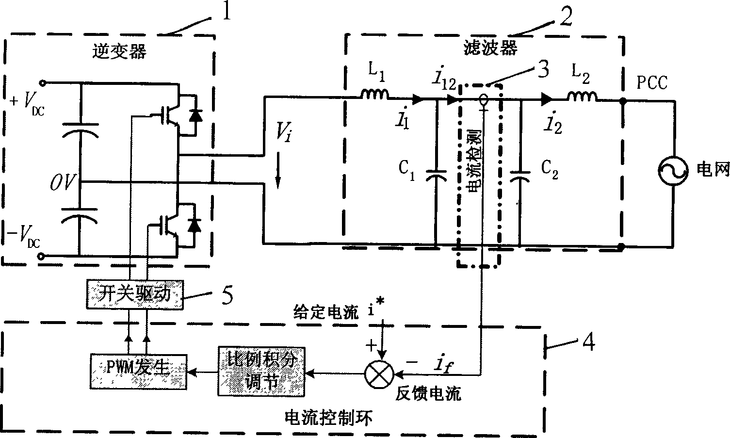
[0012] figure 2 Shown is a grid-connected inverter circuit using the method of the present invention, which includes a pulse width modulation (PWM) control single-phase inverter 1 based on high-frequency switches (in the example, the single-phase inverter is a voltage source half-bridge Type, using IGBT as power switch), low-pass filter for inverter grid-connected operation, current transducer 3 for current detection, current control loop 4 and switch for inverter grid-connected operation The driving circuit 5, wherein the current control loop 4 includes current error calculation, error signal proportional integral regulator and PWM generating circuit. The inverter output is connected to the grid through a low-pass filter. The low-pass filter is composed of a series inductor L on the inverter side. 1 , The first bypass capacitor C connected in parallel 1 And the second bypass capacitor C 2 And the grid-side series inductance L 2 T-type circuit composed of (hereinafter referred t...


PUM


Abstract

This invention discloses a method for controlling current of interconnected inverters applying current feed back, in which, a low-pass filter connected between the inverted output and a network applies a T-type circuit composed of inverse side serial inductors, two parallel by-pass capacitors and network side serial inductors, the capacitance ratio of the two by-pass capacitors is in inverse ratio to the inductance of the adjacent filter inductance and utilizes a current converter to test the current between the two by-pass capacitors and takes it as the feed back signal for the inverse output current control to be compared with the given signal of the network current then to be input into a ratio integral adjuster and takes the output signal after the adjustment as the pulse width modulation signal operated by the inverse switch to control the output waveforms and amplitude value of the interconnection inverter.

Description

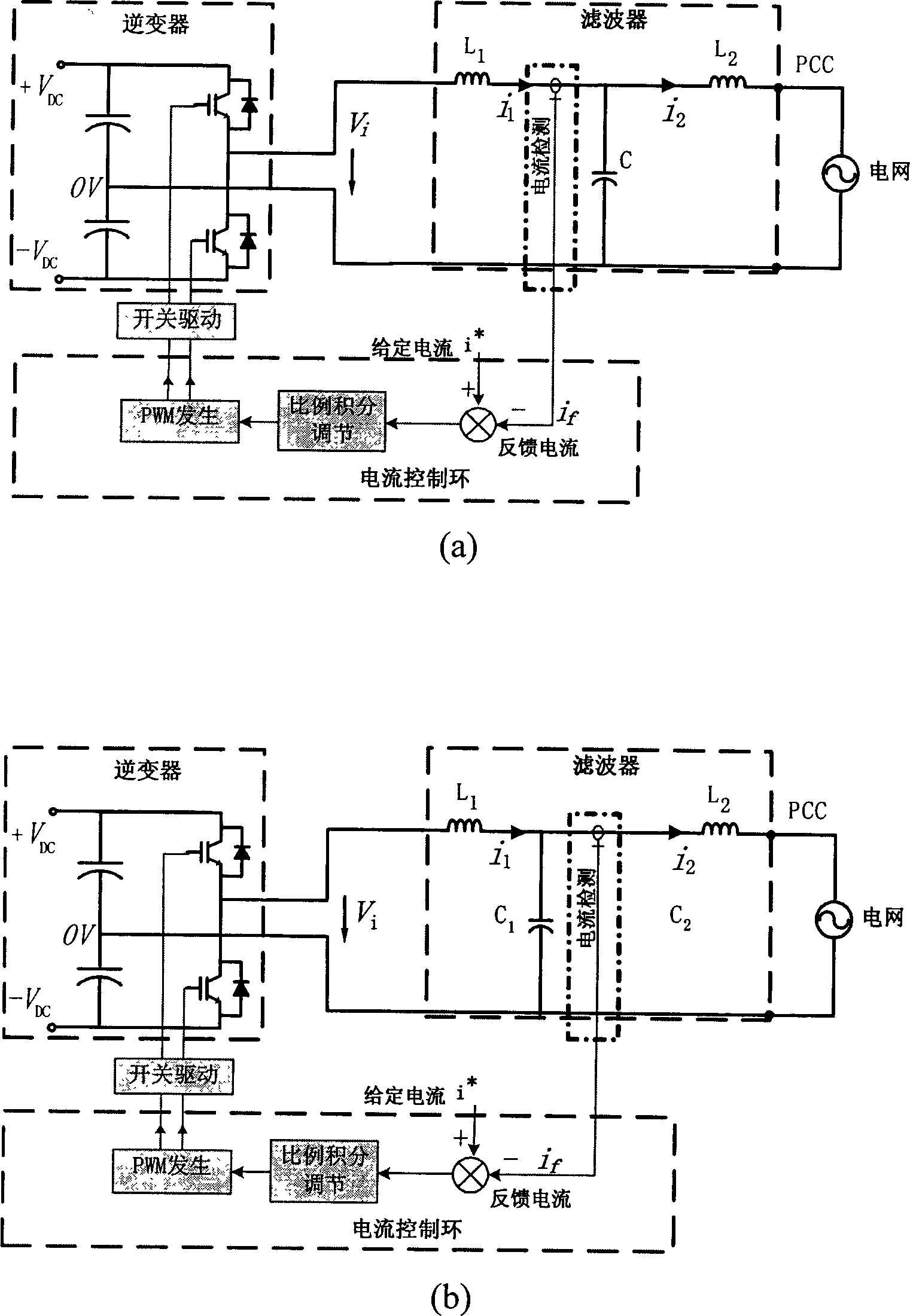
Technical field [0001] The invention relates to a grid-connected inverter control method, in particular to a grid-connected inverter current control method using filter intermediate current feedback. Background technique [0002] Inverter power supply with grid-connected power generation function, its circuit is as figure 1 As shown in (a) and (b), it usually includes PWM (Pulse Width Modulation) based on high-frequency switching to control single-phase or three-phase inverters, LCL low-pass filters for inverter and grid-connected operation, and The current transducer for current detection, the current control loop and switch drive circuit of the current error calculation and error signal proportional integral regulator used for the inverter grid-connected operation, the inverter is the output current control when the inverter is grid-connected, To ensure that the current is a strict sine wave and has a higher power factor for power generation. Traditional current control method...

Claims


Application Information

Patent Timeline
IPC IPC(8): H02J3/38
Inventor 沈国桥徐德鸿
Owner ZHEJIANG UNIV
Learn More