Method of mfg. achromatic color changed silver diffraction images
A manufacturing method and achromatic technology, applied in optical components, optics, instruments, etc., can solve the problems of needing graphic masks, unfavorable precise optical variable images, and large granularity of stripe speckle
- Summary
- Abstract
- Description
- Claims
- Application Information
AI Technical Summary
Problems solved by technology
Method used
Image


Examples
Embodiment 1
[0046] Embodiment 1: A method for making an achromatic color-changing silver diffraction image, comprising the following steps:
[0047] (1) Prepare a binary optical element, which is a pure phase diffractive optical element, and its far-field diffractive light field is a slit;
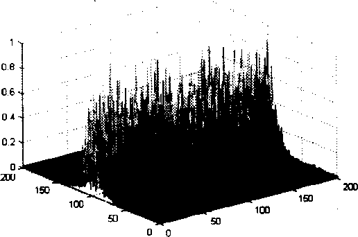
[0048] (2) Construct a 4F optical system, the light emitted by the laser light source is used as the incident light after collimation and aperture, and the recording material is placed on the image plane of the 4F optical system, and the binary optical element obtained in step (1) is placed on the On its transformation plane, as a beam splitting element, the incident light is divided into two strip-shaped light fields, and after being imaged by the lens group, a speckle interference image unit is formed on the surface of the recording material, wherein the front focal length of the 4F optical system If it is greater than the back focal length, the reduced image of the diaphragm is obtained on the imag...
Embodiment 2
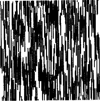
[0060] Embodiment 2: through control Figure 4 The rotating mechanism 9 in can record the speckle structures with different orientations, see the attached Figure 10 As shown, the orientations of the diffraction slits of the speckle structure with different orientations are different, so that the lithographic image has the effect of light change, that is, the color-changing silver light-change image mentioned in this patent. Figure 11 It is a real photo map of the optically variable image.
Embodiment 3
[0061] Embodiment three: replace Figure 4 The beam splitting element 7 can produce optically variable images with different effects. For example, when the beam splitting element is a one-dimensional grating, the photolithographic image has a rainbow effect; when the beam splitting element is an orthogonal grating, the photolithographic image has a rainbow effect in the two-dimensional direction (it is called an orthogonal plain rainbow in the industry) ; When the beam splitting element is a binary phase grating, the photoetched image has a color-changing silver effect. Therefore, if the photolithographic rainbow effect and the color-changing silver effect are combined into a new type of light-variable image, only different beam splitting elements need to be replaced. Since the replacement of the phase element does not affect the position of the light spot, the above method can realize any mosaic combination of the achromatic diffraction image and the rainbow diffraction opti...
PUM
 Abstract
Description
Claims
Application Information
 - R&D
- Intellectual Property
- Life Sciences
- Materials
- Tech Scout
- Unparalleled Data Quality
- Higher Quality Content
- 60% Fewer Hallucinations
Browse by: Latest US Patents, China's latest patents, Technical Efficacy Thesaurus, Application Domain, Technology Topic, Popular Technical Reports.
© 2025 PatSnap. All rights reserved.Legal|Privacy policy|Modern Slavery Act Transparency Statement|Sitemap|About US| Contact US: help@patsnap.com