Process for producing dental prosthesis and kit for use therein
A technology for dentistry and restorations, which is used in the field of manufacturing dental restorations, and can solve the problems of low mechanical strength and toughness of alumina and spinel.
- Summary
- Abstract
- Description
- Claims
- Application Information
AI Technical Summary
Problems solved by technology
Method used
Image
Examples
example 1
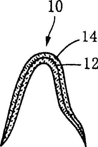
[0133] Figure 1-7 It is a schematic diagram for illustrating a method of manufacturing a crown 38 as an example of a dental prosthesis according to the first and second inventions. The crown 38 is to be fitted, for example, as an incisor in the upper jaw of an adult. The invention is also applicable to all other teeth. exist figure 1 In , a separately manufactured frame 10 (single tooth crown frame) made of zirconia was prepared. The frame 10 made of zirconia is produced by generally known methods such as forming a tooth form from plaster and pouring zirconia into the tooth form.
[0134] First, the first porcelain was uniformly coated (coated) with a brush on the above-mentioned frame 10 made of zirconia so that the first porcelain had a thickness of about 0.1 (mm). The first ceramic material used here is a slurry of ceramic powder including the ingredients shown in Table 1 given below by mixing 100 parts by mass of an aqueous propylene glycol solution with 100 parts by ...
example 2-10
[0147] In each of these examples, except that the second porcelain material having the composition shown in Table 2 and in the form of ceramic powder is used, and the viscosity of the second porcelain material at the casting temperature is shown in Table 2, the same method as in the example 1 A crown having the same configuration as Example 1 was fabricated in the same manner. It should be noted that "viscosity" in Table 2 represents the viscosity value at the casting temperature.
[0148] No.
SiO 2
al 2 o 3
K 2 o
Na 2 o
Li 2 o
B 2 o 3
CaO
CeO 2
MgO
Sb 2 o 3
ZrO 2
Viscosity (cP)
2
3
4
5
6
7
8
9
10
64.3
62.6
63.9
64.7
64.3
65.4
66.7
66.0
66.6
15.8
17.8
15.8
16.0
16.2
15.2
16.0
15.9
16.4
9.9
9.7
9.9
10.0
10.6
...
example 11
[0153] In this example, a frame made of metal is used as the base. The metal frame is composed of 78 (mass %) Au, 7.1 (mass %) Pt, 9.8 (mass %) Pd, 2.4 (mass %) Ag, and unavoidable impurities.
[0154] Also, in this example, except that the first porcelain used here includes ceramic powder made of the composition shown in Table 3 instead of the composition shown in Table 1 and the firing temperature of the lining coating layer is 980 (° C.) , The liner coating layer was formed in the same manner as in Example 1.
[0155] first porcelain
second porcelain
Ingredients
(quality%)
SiO 2
Al 2 o 3
K 2 o
Na 2 o
Li 2 o
ZrO 2
CaO
MgO
SnO 2
47.7
14.0
10.0
6.0
0.3
--
1.0
1.0
20.0
64.5
14.3
10.0
9.0
0.3
0.5
1.0
0.4
--
Viscosity at casting temperature
1.5×10 7 (c...
PUM
| Property | Measurement | Unit |
|---|---|---|
| thickness | aaaaa | aaaaa |
| thickness | aaaaa | aaaaa |
| thickness | aaaaa | aaaaa |
Abstract
Description
Claims
Application Information
 - R&D Engineer
- R&D Manager
- IP Professional
- Industry Leading Data Capabilities
- Powerful AI technology
- Patent DNA Extraction
Browse by: Latest US Patents, China's latest patents, Technical Efficacy Thesaurus, Application Domain, Technology Topic, Popular Technical Reports.
© 2024 PatSnap. All rights reserved.Legal|Privacy policy|Modern Slavery Act Transparency Statement|Sitemap|About US| Contact US: help@patsnap.com


