


Quick Research
Generate reliable direction feasibility study reports for your R&D in just a few steps.

Technical Q&A
Discover and master advanced knowledge NOW. Basics, ideas, possibilities, all at once.

Find Solutions
As an expert in R&D theories, this can generate solutions to your technical problems instantly.

Evaluate Feasibility
Analyze your overall solution with one click, know your potential R&D risks in advance.

Monitor Landscape
Get weekly tech updates, stay abreast of the latest tech innovations and key insights.
Permanent magnet motor rotor capable of automatic weaking magnet following rotation speed
A permanent magnet motor and automatic technology, applied in the direction of magnetic circuit rotating parts, magnetic circuit shape/style/structure, etc., can solve the problems of large rotor flux leakage, system efficiency drop, low torque, etc., to reduce magnetic flux leakage , Improve utilization efficiency, improve the effect of torque
- Summary
- Abstract
- Description
- Claims
- Application Information
AI Technical Summary
Problems solved by technology
Method used
Image

Examples
specific Embodiment approach 1
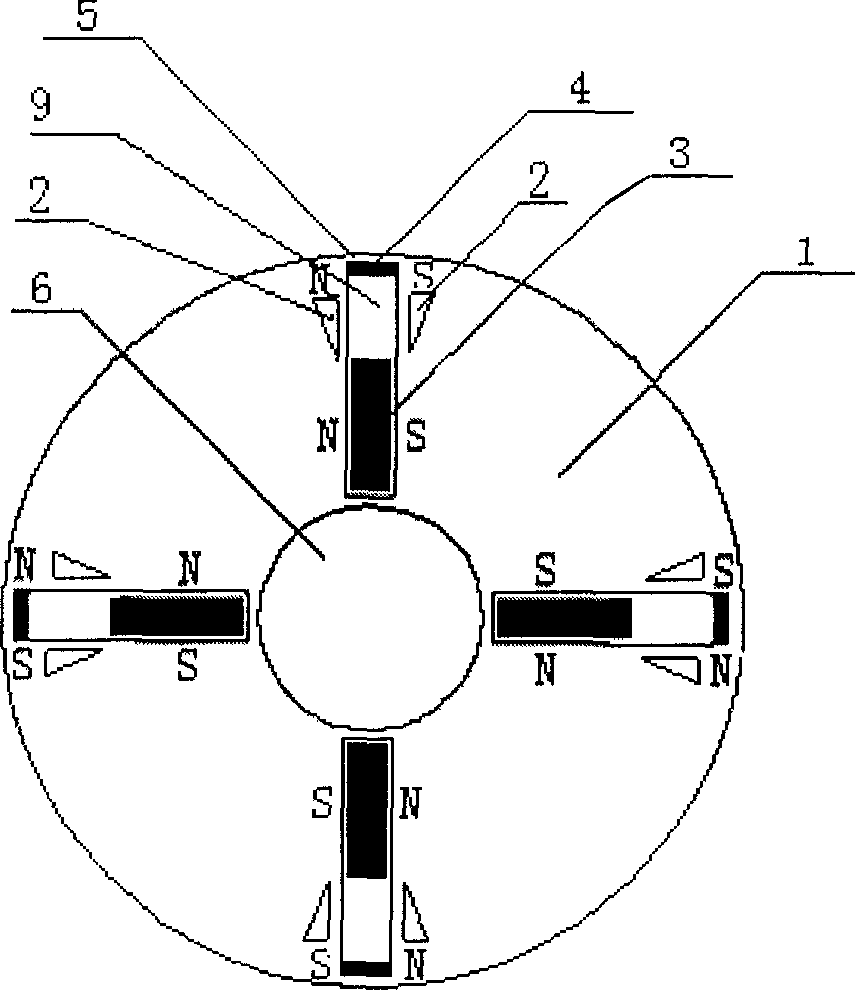
[0006] Specific implementation mode one: the following combination figure 1 This embodiment will be specifically described. It consists of a rotor core 1, several main pole permanent magnets 3, and several auxiliary permanent magnets 4. The rotor core 1 is cylindrical, and there is a shaft hole 6 for assembling the rotating shaft at the center of the rotor core 1. Several radial chutes 9 are distributed, and each radial chute 9 is inlaid with a main pole permanent magnet 3 and the main pole permanent magnet 3 is shorter than the length of the radial chute 9, and the outer surface of the radial chute 9 An auxiliary permanent magnet 4 is fixed at the end, and both the main pole permanent magnet 3 and the auxiliary permanent magnet 4 are tangentially magnetized and the magnetization direction of the main pole permanent magnet 3 and the auxiliary permanent magnet 4 in the same radial chute 9 is the same , the adjacent side surfaces of the two adjacent main pole permanent magnets...
specific Embodiment approach 2
[0007] Specific implementation mode two: the following combination figure 1 This embodiment will be specifically described. There is a magnetic isolation groove 2 on both sides of the radial chute 9, two magnetic isolation grooves 2 take the radial chute 9 as the symmetrical center, and the magnetic isolation groove 2 is opened at the outer end of the radial chute 9 . Other components and connections are the same as those in Embodiment 1. In this embodiment, "the reluctance of the rotor core 1 at the inner end of the radial chute 9 is smaller than the reluctance of the rotor core 1 at the outer end of the radial chute 9" is realized by separating the magnetic slot 2, the structure is simple, and the process is easy to realize . The function of the magnetic isolation groove 2 is to reduce the magnetic flux sent by the main pole permanent magnet 3 when the main pole permanent magnet 3 moves outwards into its position, so its size and shape are not unique, and can be rectangu...
specific Embodiment approach 3
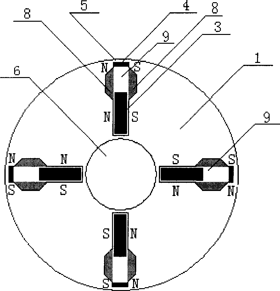
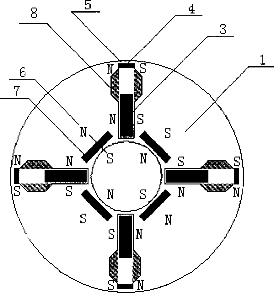
[0008] Specific implementation mode three: the following combination figure 2 This embodiment will be specifically described. The difference between this embodiment and the second embodiment is that it also includes a non-magnetically conductive plate 8 , which is arranged on both sides of the radial chute 9 and located at the outer end of the radial chute 9 . In this embodiment, "the reluctance of the rotor core 1 at the inner end of the radial chute 9 is smaller than the reluctance of the rotor core 1 at the outer end of the radial chute 9" is realized by setting the non-magnetic conductive plate 8, and the two non-magnetic conductive plates 8 is also equivalent to the auxiliary slideway of the main pole permanent magnet 3, so that the main pole permanent magnet 3 can slide smoothly in the radial slide groove 9. Other compositions and connections are the same as those in Embodiment 2.
PUM
 Abstract
Description
Claims
Application Information
 - R&D Engineer
- R&D Manager
- IP Professional
- Industry Leading Data Capabilities
- Powerful AI technology
- Patent DNA Extraction
Browse by: Latest US Patents, China's latest patents, Technical Efficacy Thesaurus, Application Domain, Technology Topic, Popular Technical Reports.
© 2024 PatSnap. All rights reserved.Legal|Privacy policy|Modern Slavery Act Transparency Statement|Sitemap|About US| Contact US: help@patsnap.com