
Signal magnifying multiple circuit with digital control

A control circuit and signal amplification technology, which is used in electrical/magnetic exploration, radio wave measurement systems, and re-radiation of sound waves. , to prevent the effect of jitter and interference

Inactive Publication Date: 2006-08-16
CENT SOUTH UNIV
View PDF0 Cites 2 Cited by
  • Summary
  • Abstract
  • Description
  • Claims
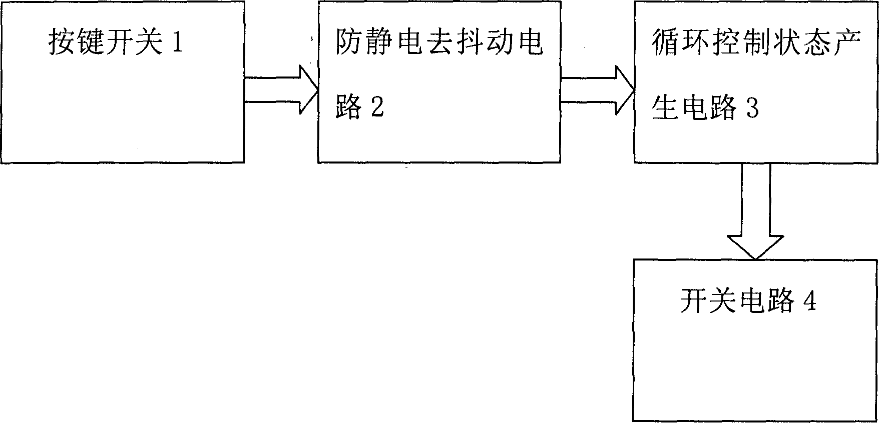
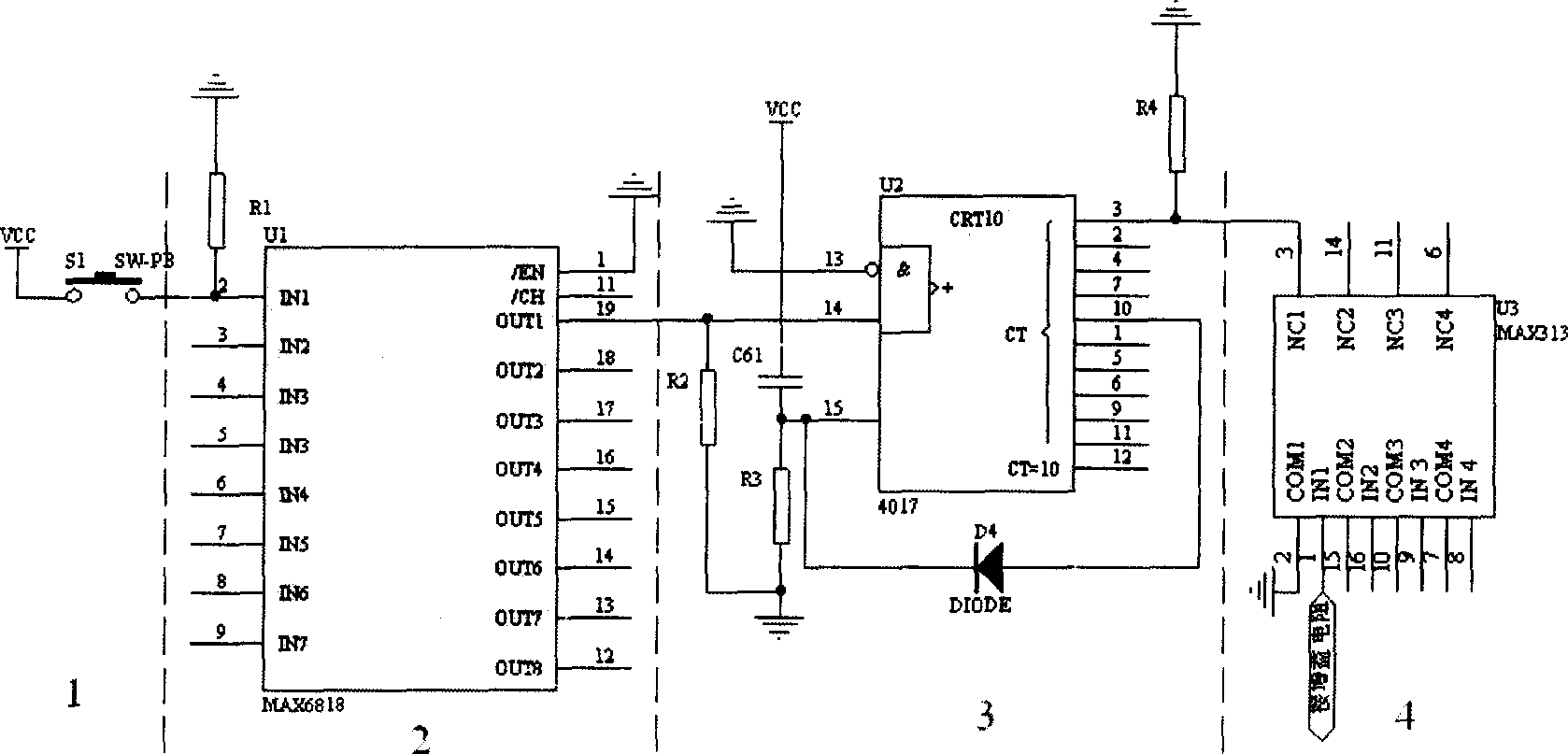
  • Application Information

AI Technical Summary

Problems solved by technology

[0002] At present, the gain control in the circuit is generally realized by a single-chip microcomputer or other microcontrollers. These devices are all digital chips, and the circuit needs to run continuously, or use multi-level switches and oscillators to generate periodic signals for control. The analog amplifier circuit is easy to cause interference; in addition, due to the vibration and static electricity when the key is pressed, the key operation will be unstable.

Method used


Image

  • Signal magnifying multiple circuit with digital control
  • Signal magnifying multiple circuit with digital control

Examples


Embodiment Construction

[0009] The present invention will be further described below in conjunction with the accompanying drawings and embodiments.

[0010] Refer to attached figure 1 , 2 , this embodiment includes a key switch 1, an anti-static debounce circuit 2, a cycle control state generating circuit 3 and a switch circuit 4; the key switch 1, an anti-static de-bounce circuit 2, a cycle control state generating circuit 3 and a switch circuit 4 Sequential connection; anti-static debounce circuit 2 includes switch debounce chip U 1 , U 1 Using the chip MAX6818, the input terminal IN of the chip MAX6818 1 through resistor R 1 ground, and the other input terminals are also grounded through resistors; at the same time, the input terminal IN 1 with key switch S 1 connection, key switch S 1 The other end is connected to the power supply V CC Connection; cycle control state generation circuit 3 includes counting / pulse distribution chip U 2 and by resistor R 3 , capacitance C 61 Composed of po...


PUM


Abstract

A control circuit of signal amplification times consists of key switch, static electricity proof and jitter removal circuit, state generation circuit of cyclic control and switch circuit .It features that above said units are connected in sequence, digital circuit is operated only when key is pressed down and it does not work at the other time for effectively avoiding interference of digital circuit to analog circuit.

Description

technical field [0001] The invention relates to a signal magnification control circuit, in particular to a state machine-based signal magnification control circuit that can be used in electrical prospecting instruments. Background technique [0002] At present, the gain control in the circuit is generally realized by a single-chip microcomputer or other microcontrollers. These devices are all digital chips, and the circuit needs to run continuously, or use multi-level switches and oscillators to generate periodic signals for control. The advanced analog amplifier circuit is prone to interference; in addition, due to jitter and static electricity when pressing the key, the key operation will be unstable. Contents of the invention [0003] The object of the present invention is to overcome the disadvantages of the above-mentioned prior art, and provide a magnification control circuit that does not interfere with the ana...

Claims


Application Information

Patent Timeline
Patent Type & Authority Applications(China)
IPC IPC(8): G01V3/00
Inventor 陈儒军颜良何继善刘石
Owner CENT SOUTH UNIV
Learn More