Rotation speed detecting device and method for brushless DC PWM fan

A fan speed and detection device technology, which is applied to the components of the pumping device for elastic fluids, devices using electric/magnetic methods, non-variable pumps, etc., can solve the trouble of testing, not suitable for assembly line operations, Take up a lot of space and other problems, to achieve the effect of small size, rich man-machine interface, and complete information display

Inactive Publication Date: 2006-08-02
HONG FU JIN PRECISION IND (SHENZHEN) CO LTD +1
View PDF0 Cites 11 Cited by
  • Summary
  • Abstract
  • Description
  • Claims
  • Application Information

AI Technical Summary

Problems solved by technology

This detection method requires a lot of equipment, takes up a lot of space, and the test is quite troublesome, and the quality of the required personnel must be high, so it is not suitable for the assembly line operation of a large number of products in the production line.

Method used


Image

  • Rotation speed detecting device and method for brushless DC PWM fan
  • Rotation speed detecting device and method for brushless DC PWM fan
  • Rotation speed detecting device and method for brushless DC PWM fan

Examples


Embodiment Construction

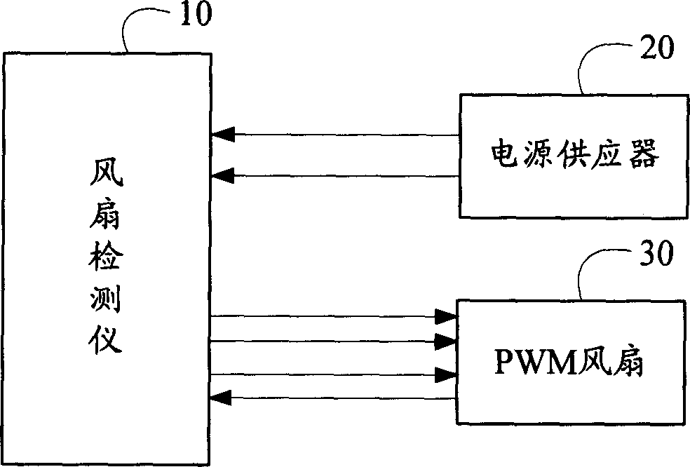
[0019] refer to figure 1 Shown is a hardware architecture diagram of the brushless DC PWM fan speed detection device of the present invention. The fan testing device includes a fan testing instrument 10 , a power supply 20 and a PWM fan 30 to be tested. Wherein, the power supply 20 provides power to the fan detector 10, and the two are connected through a power line. The detailed structure of the fan detector 10 is as follows: figure 2 shown.

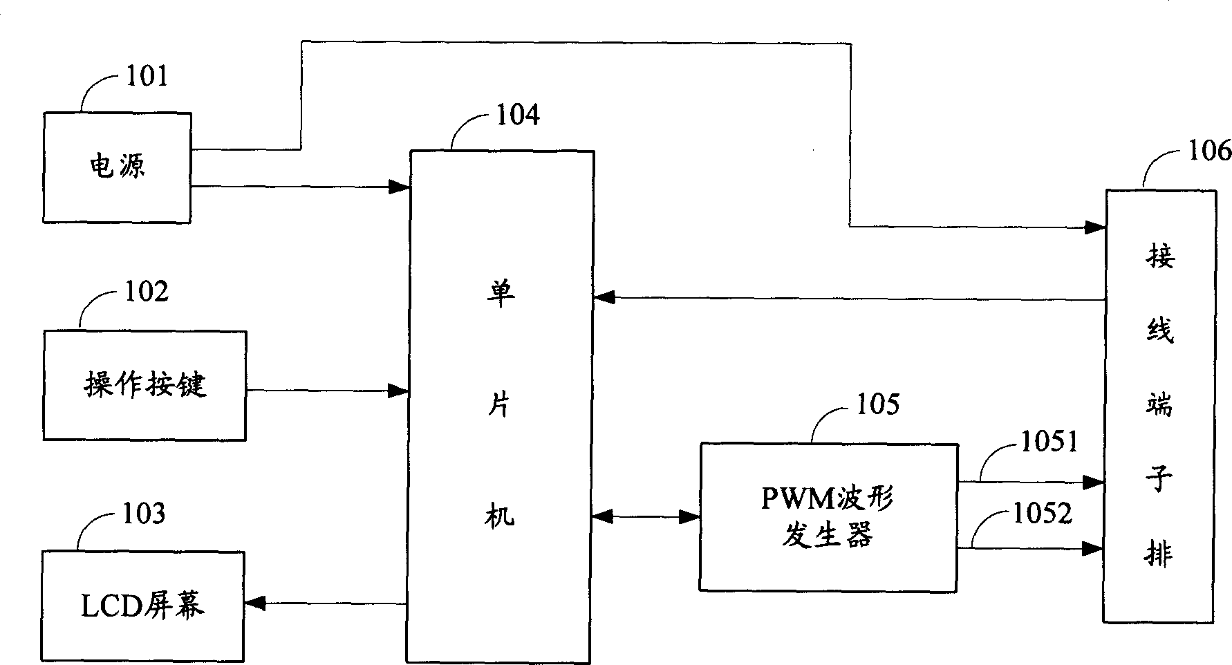
[0020] refer to figure 2 Shown is the hardware block diagram of the fan detector of the present invention. The fan tester 10 is composed of a power supply 101 , operation buttons 102 , an LCD screen 103 , a single chip microcomputer 104 , a PWM waveform generator 105 , and a terminal block 106 . Wherein the power supply 101 provides the uninterrupted power supply of the single-chip microcomputer 104 and the terminal block 106, and can save the latest PWM fan test data when the external power supply is cut off. The terminal block...


PUM


Abstract

The rotation speed detecting device for brushless DC PWM fan includes one PWM fan, one PWM fan detecting instrument and one power supply for the PWM fan detecting instrument, and the PWM fan detecting instrument consists of power source, operation buttons, LCD screen, monolithic computer, PWM waveform generator, and wiring terminal bar. The power source powers the detecting instrument and the PWM fan and makes it possible to save the last fan test data after the outer power supply is cut off; the wiring terminal bar is for connection between the detecting instrument and the PWM fan; the PWM waveform generator is connected to the monolithic computer and the wiring terminal bar; and the operation buttons and the LCD screen located in the surface of the detecting instrument are connected to the monolithic computer through data bus. The detecting method is also provided. The present invention is suitable for use in the production line.

Description

【Technical field】 [0001] The invention relates to a device and a method for automatically testing the rotational speed of a fan. 【Background technique】 [0002] PWM (Pulse Width Modulation, Pulse Width Modulation) is a control method that chops the output voltage of the converter into pulses, and changes the value and frequency of the output voltage by changing the width, number, or distribution rules of the pulses. Because the PWM fan has many advantages such as energy saving, it has become the new favorite in the field of PC system cooling. [0003] Duty Cycle (Duty Cycle) refers to the ratio of the time occupied by the high and low levels. The larger the duty cycle, the longer the circuit is turned on. The rotational speed of the PWM fan increases proportionally with the duty cycle to achieve the purpose of fan rotational speed control. [0004] However, since it is a new product, the original detection method is used, that is, the power supply is used to provide fan po...

Claims


Application Information

Patent Timeline
Patent Type & Authority Applications(China)
IPC IPC(8): F04D29/64G01P3/44
Inventor 黄登聪徐华勇
Owner HONG FU JIN PRECISION IND (SHENZHEN) CO LTD
Why Eureka
Try Eureka