
Smoke low-temperature residual heat utilization system with natural gas cooling-heating combined power device and operating method thereof

A technology for combined cooling, heating and power, and natural gas, applied in the thermal equipment and power generation fields, can solve the problems of not considering the combined supply of domestic hot water, no engineering practical value, poor technical and economic performance, etc., to improve flexibility and economy, large benefit, and the effect of improving power generation output

Inactive Publication Date: 2006-07-26
SOUTH CHINA UNIV OF TECH
View PDF4 Cites 51 Cited by
  • Summary
  • Abstract
  • Description
  • Claims
  • Application Information

AI Technical Summary

Problems solved by technology

Although the patent application document mentions that the exhaust gas temperature from the system through the condensing heat exchanger is about 30°C, the document does not fully disclose the technical measures taken to achieve such a low exhaust gas temperature, because if the traditional To achieve the above-mentioned low-temperature smoke exhaust by partition wall heat exchange, a huge amount of steel is required, which has no engineering practical value at all.
[0013] It can also be seen from the above examples that the current combined cooling, heating and power supply equipment system either does not consider the joint supply of domestic hot water supply, or uses the traditional partition wall waste heat boiler to provide hot water, which is bound to be left out due to poor technical and economic performance. abandon

Method used


Image

  • Smoke low-temperature residual heat utilization system with natural gas cooling-heating combined power device and operating method thereof
  • Smoke low-temperature residual heat utilization system with natural gas cooling-heating combined power device and operating method thereof
  • Smoke low-temperature residual heat utilization system with natural gas cooling-heating combined power device and operating method thereof

Examples


Embodiment Construction

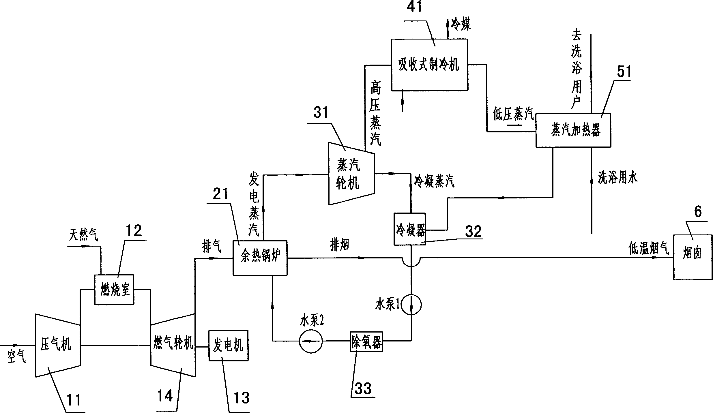
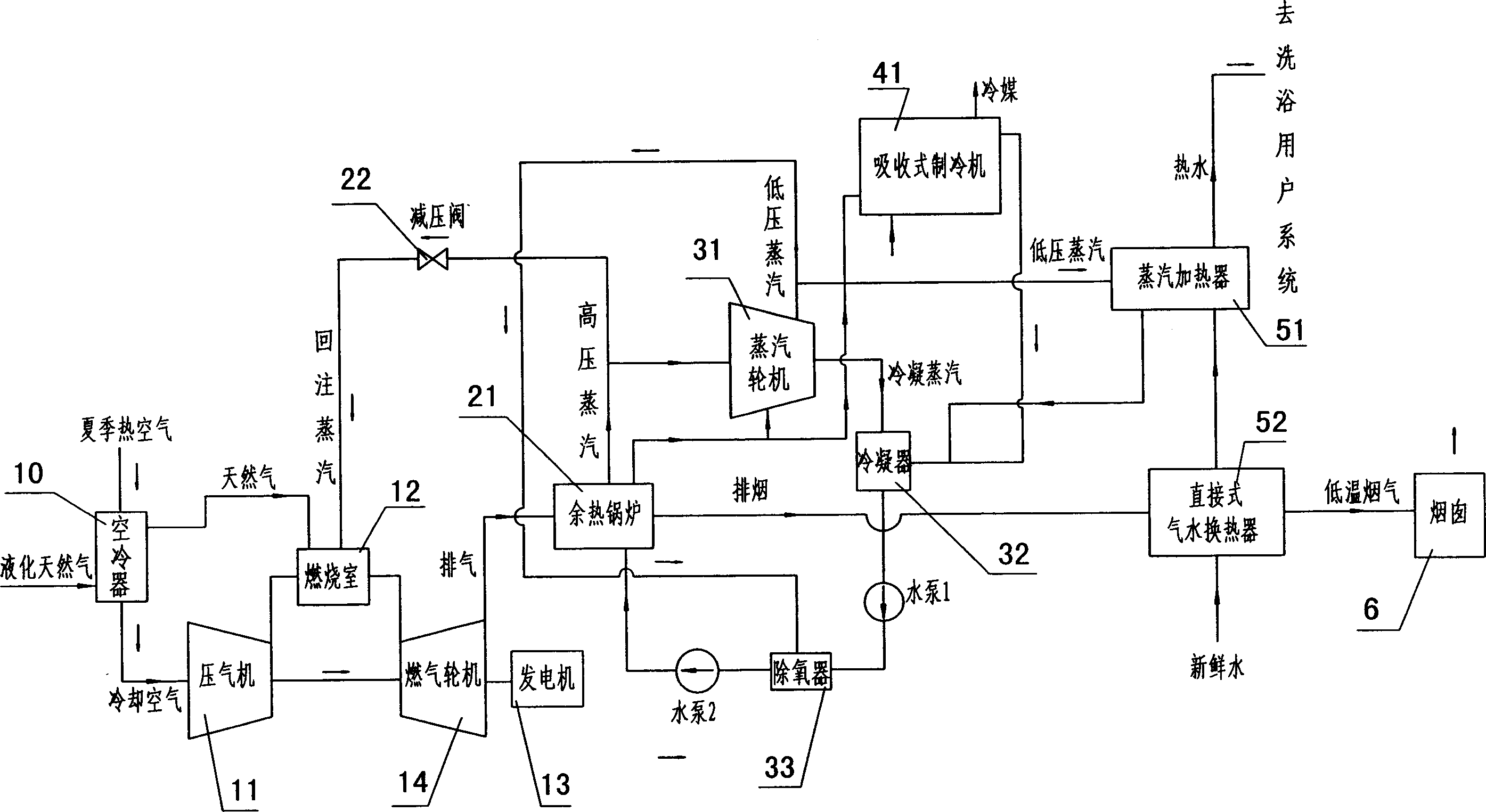
[0043] like figure 2, which shows the structure of a preferred embodiment of the flue gas low-temperature heat utilization system of combined cooling, heating and power supply of the present invention. The heat utilization system includes a gas-fired power generation device, a waste heat boiler, an absorption refrigeration device, and a heating water supply device; The power generation device includes a compressor 11, a combustion chamber 12, a generator 13, and a gas turbine 14; the inlet of the compressor 11 is connected to the atmosphere, and its outlet 11 is connected to the inlet of the combustion chamber 12; the inlet of the combustion chamber 12 is also connected to the natural gas nozzle The waste heat boiler 21 includes a flue gas inlet, a flue gas outlet, a condensed water inlet and a steam outlet. The steam path and pipeline of the pipe, steam turbine 31 are connected with the absorption refrigeration device 41 and the steam heater 51 as the heating water supply de...


PUM


Abstract

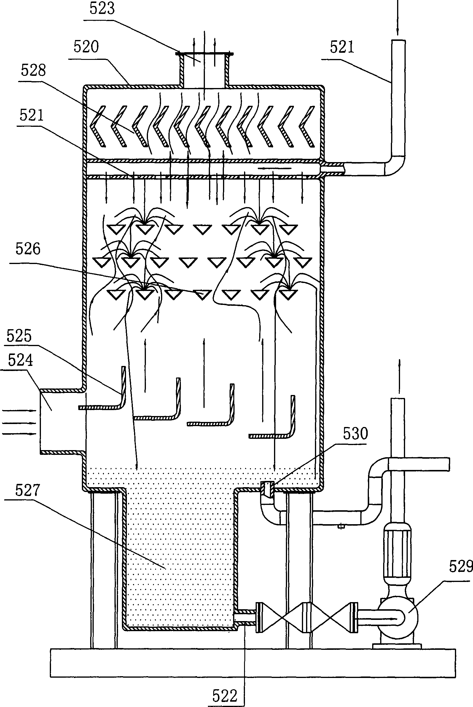
The invention relates to a smoke low-temperature heat utilization system of natural gas cold-heat electric supply and relative operation method. Said system comprises a fuel gas generator, a waste heat boiler, an adsorption refrigerator, and a heating water supply device. Wherein, the heating water supply device comprises a direct gas-water heat exchanger which contains a gondola water faucet whose water channel forms the smoke channel; the smoke outlet of waste heat boiler is connected to the chimney via the direct gas-water heat exchanger; the water inlet and outlet pipes of direct gas-water heat exchanger are serially connected to the pipe of life hot water or water supply; the gas transmission pipe of waste heat boiler has a branch of the reflux gas pipe connecting the burning of fuel gas generator; and the reflux gas pipe is serially connected with a depressurizing device. The invention has simple heat transmission device, lower cost, improved heat efficiency and improved economic benefits.

Description

【Technical field】 [0001] The invention relates to power generation and thermal equipment, and more specifically, the invention relates to a direct heat exchange system for efficiently utilizing low-temperature waste heat from exhaust gas of a natural gas cogeneration device and domestic hot water. 【Background technique】 [0002] With the implementation of the energy strategy of vigorously developing and introducing natural gas resources and optimizing the energy structure in my country, the combined cooling, heating and power system of gas turbines using natural gas as the primary energy is developing rapidly in China. Ordinary gas turbine combined heat, power and cooling system includes gas turbine generator set, waste heat boiler, steam turbine or absorption refrigeration device; the final flue gas discharge temperature of the system is usually around 130°C, and this part of the flue gas still accounts for about 10% of the total heat energy of the fuel. Thermal utilization...

Claims


Application Information

Patent Timeline
IPC IPC(8): F02C6/18F01K23/06F01K23/10F25B27/02F24D3/00
CPCY02E20/16Y02E20/18Y02A30/274Y02E20/14
Inventor 华贲刘效洲
Owner SOUTH CHINA UNIV OF TECH
Learn More